Engineering Challenge
Urban open multi-level parking garages are being increasingly exposed to episodes of rainfall that are of short duration but have high intensity. As opposed to indoor parking garages, these parking garages offer partial or complete exposure of the roof and parking levels, resulting in runoff mechanisms that are much more complex. At the same time, these parking garages are being called upon to accommodate additional systems, such as photovoltaics, and water management, making these systems much more interdependent.
The engineering challenge that this research seeks to address is not that of individual component design, but rather that of system sizing logic across multiple systems. The decision-making process related to one component, such as storage volume, pump size, or photovoltaic (PV) size, has direct implications or constraints on other related components. In reality, this is done implicitly or sequentially, making this system more difficult to reason, adapt, or modify, particularly when boundary conditions change, such as more extreme rainfall events.
Purpose
The purpose of this parametric model is to support the integrated design of water management and energy systems within open multi-storey parking structures exposed to high-intensity rainfall. The model is intended to make the dependencies between drainage, storage, pumping, and on-site photovoltaic energy generation explicit, allowing early-stage design decisions to be evaluated at a system level rather than through isolated component sizing.
Utilizing Dynamo, the model creates a structured and flexible framework that combines rainfall characteristics, contributing areas, hydraulic elements, and energy demand from pumps with photovoltaic supply within one workflow. The model combines normal operating conditions with controlled extreme event behavior, showing how core elements behave stably while safety mechanisms such as overflow channels and culverts are only activated when necessary. Overall, the model helps improve our understanding of integrated civil engineering systems as a whole, providing a clear basis for scenario comparisons, coordination, and potential future extensions.
Added Systems
The following systems were required to be added to enable the integration logic between the original systems. They do not exist as independent systems, and their only role is connection between the original systems:
- Internal and External Drainage System
- Floor drainage channels
- Vertical Gutter/Downpipes
- Collection of rainfall from exposed parking decks and roof edges
- Controlled flow of rain water
- Storage Tank System
- Closed Tank used to temporarily store rain water
- Enables controlled drainage
- Pump System
- Size is based on target drainage time for rainfall events
- Gets its energy from PV panels
- Overflow Open Channel
- Connects the Culvert with the other systems
- Required only when inflow exceeds the capacity, during extreme rainfall
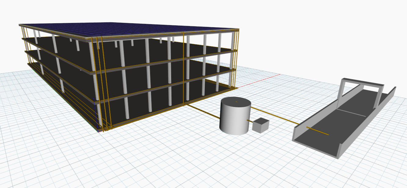
High Performance Criteria
Operational Stability in Normal Conditions
The key performance criterion is that the system is capable of collecting, storing, and draining all runoff generated in normal conditions without using emergency devices. All key components of the system, including internal conduits, gutter piping, storage reservoir, pump, and photovoltaic array, are designed only once and do not change. A system with high performance meets this criterion without surcharge, overflow, and safety devices.
Fail-Safe Response in Extreme Rainfall Conditions
For extreme rainfall conditions, high performance is characterized by the predictable and controlled operation of safety devices. The main system is intact, and excess water is diverted through an open overflow channel and discharged into the culvert. The system shows good performance when emergency devices handle excess water and do not compensate for deficiencies in the key system design.
Hydraulic Capacity of Drainage Infrastructure
For high performance, it is required that all pipes, channels, and culverts have sufficient cross-sections to transport their designed flows at reasonable velocities and with constructible geometries. The diameter of the downpipes, depths of the channel, and dimensions of the culverts must satisfy continuity conditions and satisfy minimum geometric constraints. Overdesigning is considered as an indicator of poor performance.
Energy Sufficiency of the Photovoltaic-Pump System
The photovoltaic system is designed specifically for supplying energy sufficient for operating the pump and not for supplying energy for building demand. The system with high performance is sufficient for supplying energy for operating the pump energy demand in normal conditions and is also reasonable in terms of energy and number of photovoltaic panels. It is functionally integrated and not used as mere decoration.
Dynamo Logic and Process
Grouping and Organization
- Inputs: building areas, number of floors, and effective contributing factors.
- Rainfall scenarios: normal and extreme intensity-duration pairs.
- Design constants: tank freeboard, pump parameters, conveyance velocities, and geometric minimums.
- Scenario dictionaries: dictionaries using ontology-style keys (e.g., hasRainfallIntensity, hasRainfallDuration).
- Effective area and flow calculations.
- Tank sizing and pump sizing.
- Solar sizing from required pump energy.
- Overflow logic and sizing of open channel and culvert.
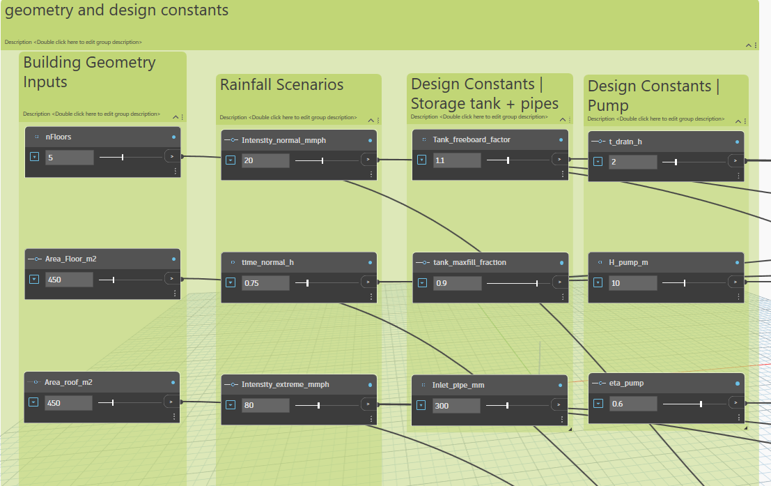
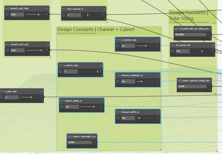
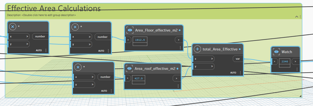
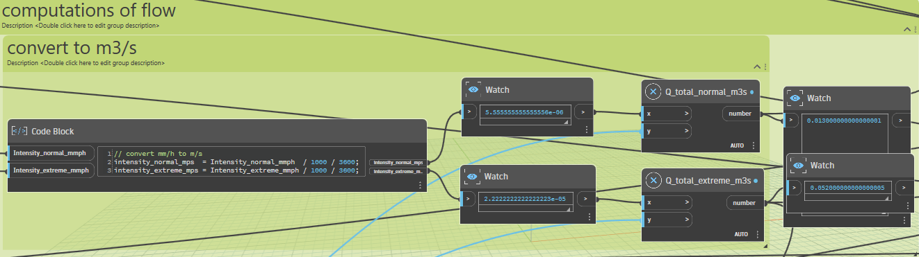
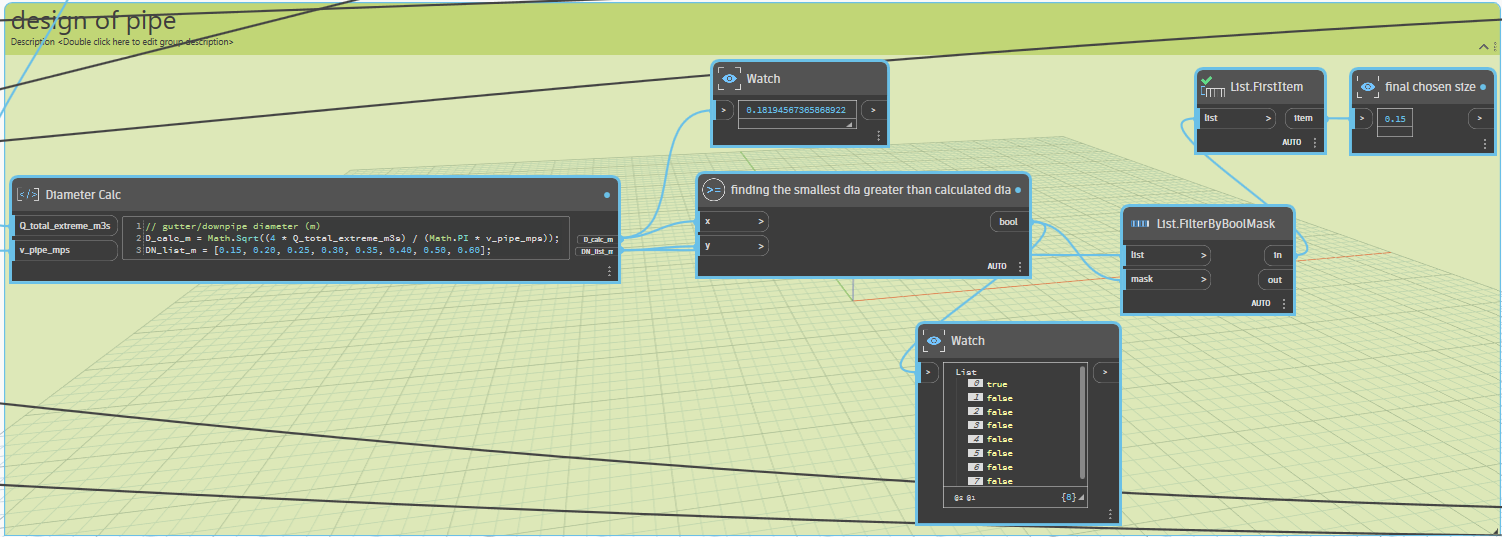
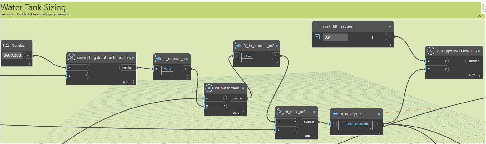
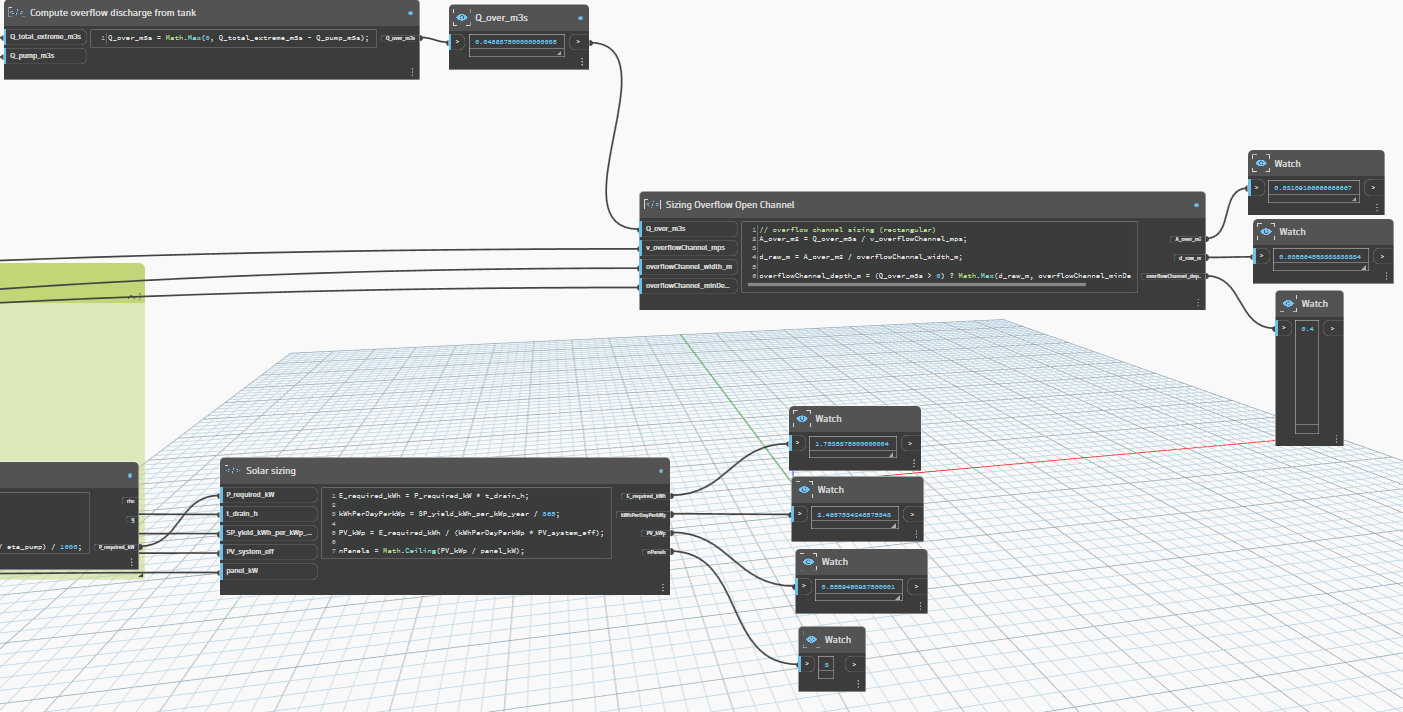
Inputs stored
| Dynamo input | Description | Default | Unit | Range (min–max) |
| nFloors | Number of floors considered as contributing surfaces. | 5 | – | 1 – 12 |
| Area_Floor_m2 | Plan area per floor (used in contributing area calculation). | 800 | m² | 150 – 1500 |
| Area_roof_m2 | Roof plan area. | 800 | m² | 150 – 1500 |
| Runoff_coeff_floor | Effective capture fraction for floors (side entry). Not a material runoff coefficient; see Section 6.2. | 0.35 | – | 0.35 – 1 |
| Runoff_coeff_roof | Roof runoff coefficient (impervious roof default). | 0.95 | – | 0.7 – 1 |
| Intensity_normal_mmph | Normal scenario rainfall intensity. | 20 | mm/h | 5 – 40 |
| time_normal_h | Normal scenario duration. | 1 | h | 0.25 – 3 |
| Intensity_extreme_mmph | Extreme scenario rainfall intensity (stress-test). | 100 | mm/h | 40 – 200 |
| time_extreme_h | Extreme scenario duration. | 1 | h | 0.25 – 3 |
| Tank_freeboard_factor | Margin factor applied to design volume to obtain maximum tank volume. | 1.1 | – | 1 – 1.3 |
| t_drain_h | Target time to drain the normal-event volume using the pump. | 2 | h | 0.5 – 8 |
| H_pump_m | Assumed pumping head (static + minor losses). | 10 | m | 2 – 25 |
| eta_pump | Overall pump efficiency used in power calculation. | 0.6 | – | 0.3 – 0.8 |
| v_pipe_mps | Assumed velocity used for downpipe diameter calculation. | 2 | m/s | 0.5 – 3 |
| v_channel_mps | Assumed velocity for overflow channel sizing. | 1.5 | m/s | 0.5 – 2.5 |
| Channel_width_m | Rectangular overflow channel width. | 0.8 | m | 0.25 – 5 |
| Channel_mindepth_m | Minimum overflow channel depth constraint. | 0.4 | m | 0.2 – 1 |
| v_culvert_mps | Assumed velocity for box culvert sizing. | 0.75 | m/s | 0.75 – 3 |
| Culvert_width_m | Box culvert width. | 0.5 | m | 0 – 21.2 |
| culvert_minHeight_m | Minimum culvert internal height. | 0.6 | m | |
| SP_yield_kWh_per_kWp_year | Specific annual yield used for Berlin-like conditions. | 900 | kWh/kWp·year | |
| SP_system_eff | System performance factor (losses/derate). | 0.8 | – | 0.6 – 0.95 |
| panel_capacity_rating_kW | Rated DC capacity per PV module/panel. | 0.4 | kW |
Scenarios
To keep the Dynamo model aligned with the ontology discussion, the graph stores the two rTo maintain consistency between the ontology and the parametric implementation, the Dynamo model represents rainfall events as explicit design scenarios. Each scenario is stored as a Dynamo dictionary, allowing rainfall conditions to be treated as structured system inputs rather than isolated numerical values.
Scenario Definition Structure
Each rainfall scenario is defined using ontology-aligned keys:
- hasRainfallIntensity (mm/h)
- hasRainfallDuration (h)
This structure mirrors the conceptual model, where scenarios are treated as system states that activate different behaviors within the integrated system.
Implemented Scenarios
Extreme Rainfall Scenario
Represents a stress-test condition used to activate safety elements, namely the overflow open channel and the culvert, without modifying the core system configuration.
| Output | Value | Unit |
|---|---|---|
| Effective contributing area, A_eff | 2160 | m² |
| Extreme inflow, Q_total_extreme | 0.06 | m³/s |
| Overflow rate, Q_over | 0.054 | m³/s |
| Selected downpipe DN (nearest) | 0.2 | m |
| Overflow channel depth | 0.4 | m |
| Culvert height | 0.6 | m |
| Culvert capacity check | 0.225 | m³/s |
Normal Rainfall Scenario
Represents routine heavy-rain conditions used for sizing the core system components (pipes, storage tank, pump, and photovoltaic system).
| Output | Value | Unit |
| Effective contributing area, A_eff | 2160 | m² |
| Normal inflow, Q_total_normal | 0.012 | m³/s |
| Normal event volume, V_design | 43.2 | m³ |
| Tank maximum volume with freeboard, V_max | 47.52 | m³ |
| Pump flow required, Q_pump | 0.006 | m³/s |
| Pump power required, P_required | 0.981 | kW |
| Pump energy over drain time, E_required | 1.962 | kWh |
| PV size, PV_kWp | 0.9946 | kWp |
| PV panels (0.4 kW each), nPanels | 3 | count |
| Extreme inflow, Q_total_extreme | 0.06 | m³/s |
| Overflow rate, Q_over | 0.054 | m³/s |
| Selected downpipe DN (nearest) | 0.2 | m |
| Overflow channel depth | 0.4 | m |
| Culvert height | 0.6 | m |
| Culvert capacity check | 0.225 | m³/s |
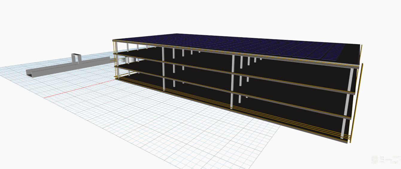
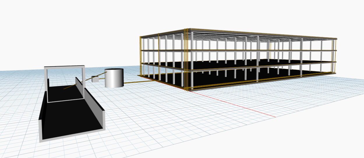
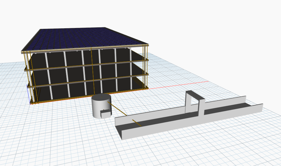
Different angles of the model:
References
- [1] Deutscher Wetterdienst (DWD). (n.d.). Warnkriterien: Starkregen. https://www.wettergefahren.de/warnungen/unwetterwarnkriterien.html
- [2] Federal Highway Administration (FHWA). (2024). Urban Drainage Design Manual (HEC-22), 4th edition (HIF-24-006). https://www.fhwa.dot.gov/engineering/hydraulics/pubs/hif24006.pdf
- [3] Federal Highway Administration (FHWA). (2022). Curb-Opening Inlet Interception On Grade (TechNote FHWA-HRT-22-061). https://www.fhwa.dot.gov/publications/research/infrastructure/22061/22061.pdf
- [4] Dobos, A. P. (2014). PVWatts Version 5 Manual. National Renewable Energy Laboratory (NREL). https://pvwatts.nrel.gov/downloads/pvwattsv5.pdf
- [5] Fraunhofer ISE. (2025). Recent Facts about Photovoltaics in Germany. https://www.ise.fraunhofer.de/content/dam/ise/en/documents/publications/studies/recent-facts-about-photovoltaics-in-germany.pdf
- [6] Penn State (EME 811). (n.d.). Pumping Power Considerations. https://courses.ems.psu.edu/eme811/node/710
- [7] U.S. Department of Energy. (2005). Improving Pumping System Performance: A Sourcebook for Industry (2nd ed.). https://energy.gov/sites/prod/files/2014/05/f16/pump.pdf
- [8] Trina Solar. (2020). Vertex module datasheet TSM-DE09 (390–405 W). https://static.trinasolar.com/sites/default/files/EN_Datasheet_Vertex_DE09.pdf
Main | Introduction | Individual Systems | Integration Context | Combined Ontology | Combined Parametric Model | Analysis and Conclusions | References