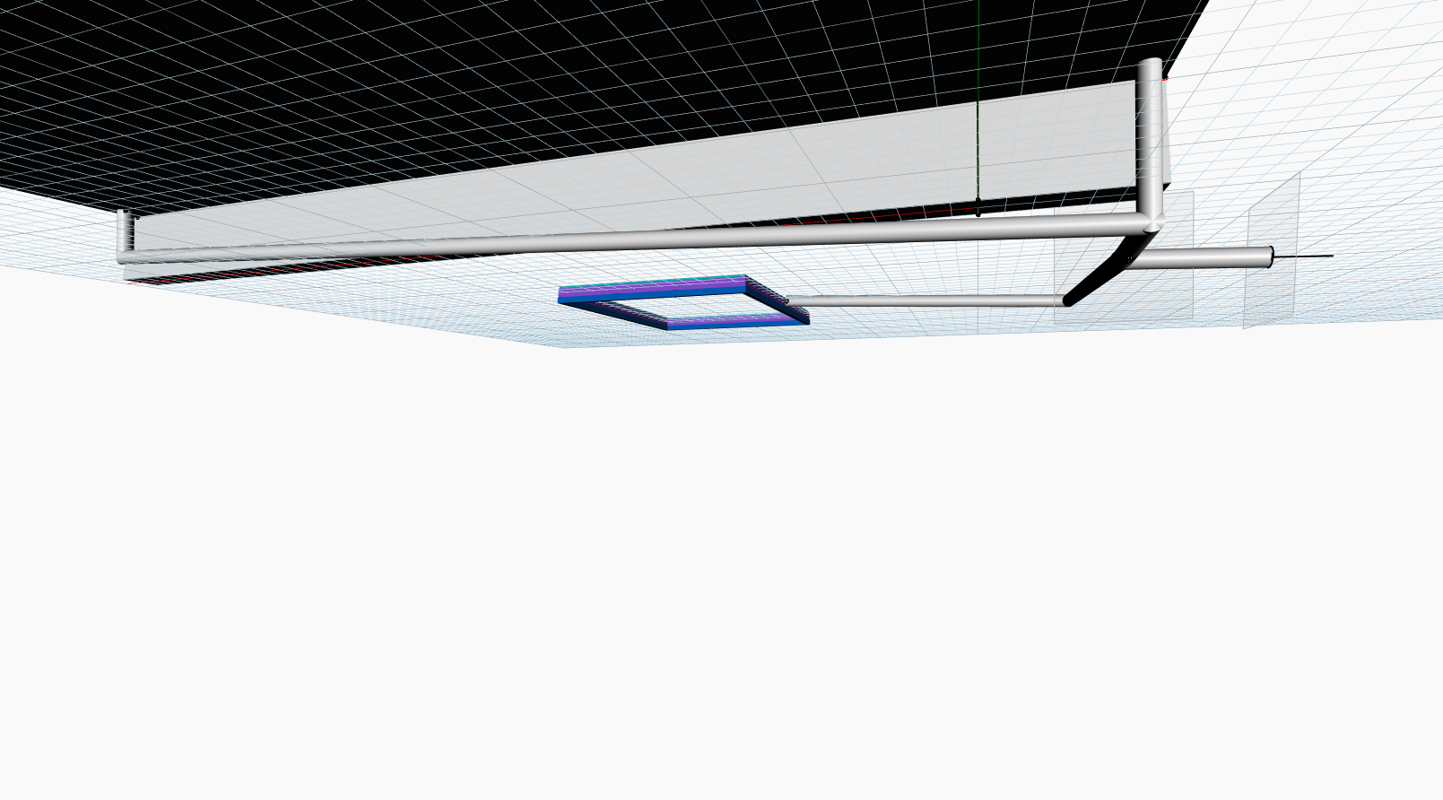
Figure 1: Integrated drainage pipe layout beneath the platform, showing gravity-driven flow routing toward the outlet.
Purpose and role in integrated system
HF2 evaluates the feasibility and robustness of the drainage subsystem under gravity-driven conditions in a high-terrain, rainfall-dominated context. It functions as an early-stage screening tool by first checking basic gravity viability through flow direction, slope, and pipe diameter. Given the remote, high-terrain, and predominantly rainy context, effective gravity drainage is essential to limit water accumulation near the retaining wall and the foundation and to reduce long-term deterioration risks, as gravity-based systems are widely recognized as the most reliable and low-maintenance solution in such environments [1]. In addition, a Manning-based full-flow calculation provides indicative capacity and velocity to compare alternative pipe configurations, helping identify options with greater performance margins and lower sensitivity to sedimentation, without representing required design discharge.
Scope and modelling level
HF2 is formulated as an early-stage assessment of gravity-driven drainage feasibility within a high-terrain, rainfall-dominated context. The model checks basic functional viability through flow direction, minimum slope, and pipe diameter, without detailed hydraulic or runoff modelling. A simplified Manning full-flow calculation is additionally used to derive indicative capacity and velocity, enabling comparison of alternative pipe configurations in terms of robustness and sedimentation tolerance rather than required design discharge.
- HF2-A: Gravity Functionality Check (binary)
The pipe slope and diameter are implemented as sliders, enabling systematic variation across predefined ranges. These parameters directly influence both the gravity functionality checks and the Manning-based capacity results. By adjusting these inputs, the model allows rapid evaluation of how geometric changes affect drainage feasibility and relative robustness without introducing rainfall-runoff complexity. This figure displays the parametric controls used to explore different drainage scenarios.
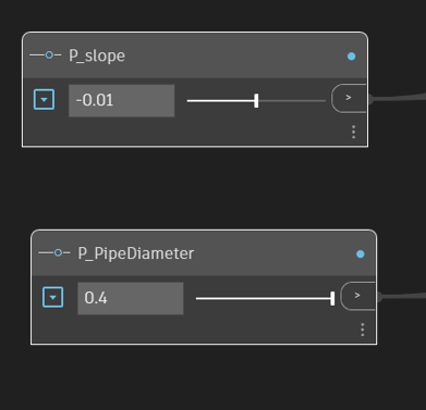
Figure 2: Parametric control of pipe slope and diameter used in the HF2 drainage assessment.
The Z-coordinates of the start and end points are compared directly to ensure that the pipe slopes downward in the intended flow direction. A positive elevation drop indicates gravity-consistent flow, while a reversed elevation difference immediately flags the configuration as non-functional. This check prevents physically inconsistent drainage layouts from being classified as valid, regardless of slope magnitude or diameter. This figure highlights the direction check used in HF2.
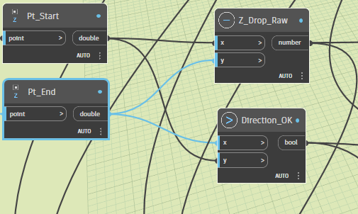
Figure 3: Verification of flow direction using start and end point elevations in the HF2 gravity check.
The start and end elevations are extracted to determine flow direction, ensuring that gravity acts in the intended direction. The actual slope is calculated from the elevation difference and pipe length and compared against a minimum slope threshold to verify sufficient gravitational driving force. In parallel, the pipe diameter is checked against a minimum allowable value to reduce blockage risk. The results of these checks are combined to produce a binary output indicating whether segment AE is gravity-functional. This figure illustrates the gravity checks applied to pipe segment AE. his figure illustrates the gravity checks applied to pipe segment AE.
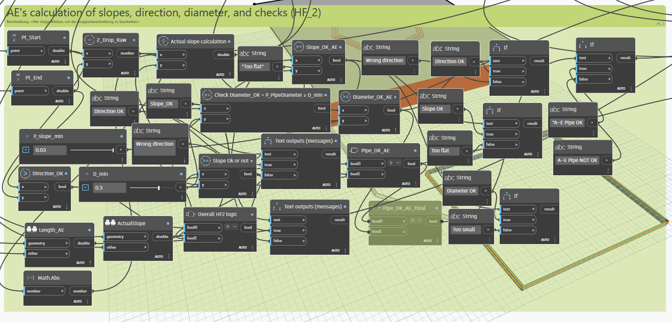
Figure 4: Gravity-functionality checks for pipe segment AE, combining direction, slope, and diameter conditions in HF2.
As with segment AE, the model verifies correct flow direction, computes the actual slope based on geometry, and checks the diameter against a minimum threshold. Each condition is evaluated independently, and the outcomes are combined to classify segment BH as either functional or non-functional under gravity. Treating AE and BH separately allows local issues within individual segments to be identified while maintaining a system-level perspective. This figure presents the equivalent gravity-functionality logic for pipe segment BH.
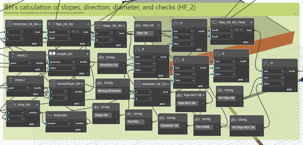
Figure 5: Gravity-functionality checks for pipe segment BH, combining direction, slope, and diameter conditions in HF2.
The outputs of the individual pipe segment checks (AE and BH) are combined using a logical AND operation to determine whether the entire drainage system functions under gravity. If both segments satisfy the required conditions, the system is flagged as gravity-drainage functional; otherwise, a warning message is returned prompting inspection of flow direction, slope, or diameter. This approach ensures that the drainage system is only considered functional when all constituent segments meet the gravity criteria. This figure shows the system-level gravity functionality check for the drainage pipe.
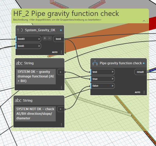
Figure 6: System-level gravity functionality check combining pipe segments AE and BH in HF2.
The pipe cross-sectional area and hydraulic radius are derived from the selected diameter, while a constant roughness coefficient representative of HDPE pipes is set to be 0.011 [1]. The average slope of segments AE and BH is used as the energy slope, allowing the computation of an indicative full-flow discharge. This calculation does not represent required flow but provides a consistent basis for comparing drainage capacity across different pipe diameters and slopes.
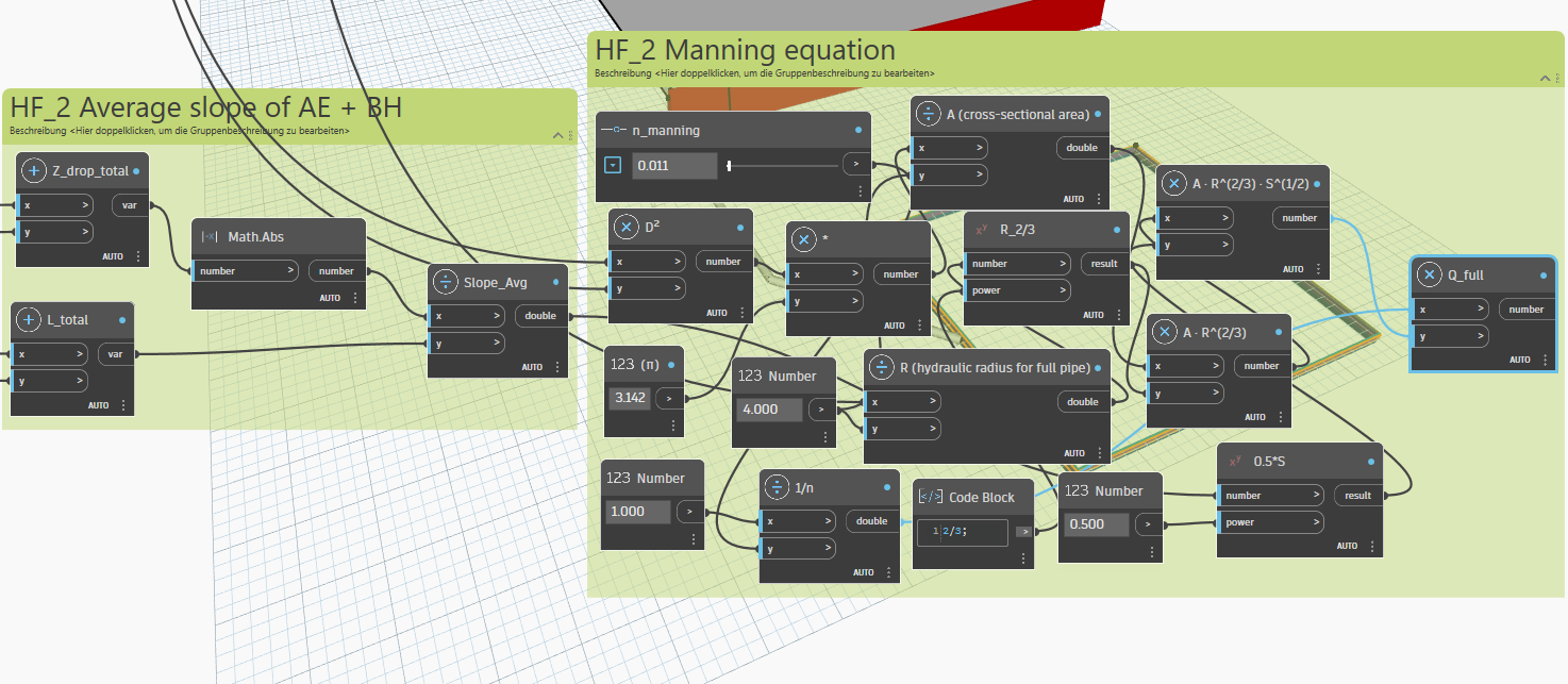
Figure 7: Implementation of the Manning-based full-flow capacity calculation using the average slope of pipe segments AE and BH in HF2.
HF2 Scenario Definition and Parametric Study
HF2 defines a parametric study based on pipe slope, diameter, and material roughness, as these parameters govern the feasibility and robustness of gravity-driven drainage in high-terrain, rainfall-prone environments. Gravity drainage is preferred due to its reliability and low maintenance requirements compared to mechanically assisted systems. The study adopts slope values between 0.5–2.0% [2,3]and pipe diameters of 150–400 mm [1,3], reflecting commonly recommended ranges that balance hydraulic performance, constructability, and clogging risk. HDPE pipes are selected for their durability and smooth internal surface, with a conservative Manning roughness value of n = 0.011, providing a realistic, literature-informed basis for early-stage drainage screening without implying detailed hydraulic design or regulatory compliance.
Manning equation background
The gravity-flow capacity of the drainage pipe is evaluated using the Manning equation, which is explicitly presented and documented in standard drainage and hydraulic engineering literature. Butler and Davies describe the Manning formulation as a primary method for estimating discharge in gravity-driven drainage pipes, relating flow rate to pipe geometry, slope, and surface roughness under steady, uniform flow conditions. The equation is given as
Q=1/n.AR2/3S1/2
where Q is the flow rate, n is the Manning roughness coefficient, A is the cross-sectional area, R is the hydraulic radius, and SSS is the pipe slope. The Manning formulation is taken directly from standard hydraulic engineering literature and is applied in this project to enable comparative assessment of drainage capacity across different pipe configurations rather than design-level verification [1].
Parametric implementation in Dynamo
The drainage system is implemented in Dynamo using a parametric approach, where the pipe slope and diameter are defined as adjustable input parameters through sliders. This allows systematic variation of these key variables across multiple scenarios while keeping the underlying geometry and logic consistent. By controlling slope and diameter parametrically, the model enables rapid exploration of different drainage configurations without manual re-modeling.
The remaining geometric properties required for the analysis, including start and end elevations and pipe length, are derived directly from the modeled pipe geometry. Elevations are extracted from the pipe endpoints, and the actual slope is computed from the elevation difference divided by the pipe length. This ensures that all calculations remain geometry-driven and automatically update in response to any changes in the model.
Using this setup, all HF2 scenarios are generated consistently from the same parametric framework, ensuring that differences in results are attributable solely to changes in slope and diameter rather than modeling inconsistencies. This approach provides a transparent and reproducible basis for comparing gravity functionality and flow capacity across scenarios.
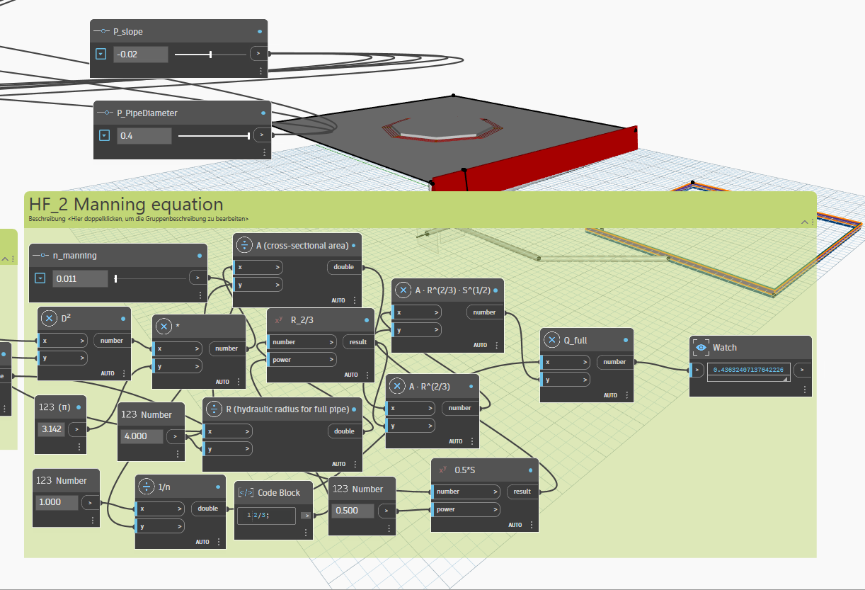
Figure 8: Parametric evaluation of Manning full-flow discharge showing the response of drainage capacity to changes in pipe slope and diameter in HF2.
This figure shows the implementation and verification of the Manning full-flow equationin Dynamo for a pipe diameter of 400 mm and a slope of 2 % (S = 0.02). The pipe diameter and slope are supplied through parametric sliders, while a Manning roughness value of n = 0.011 is used to represent a hydraulically smooth HDPE pipe. From the selected diameter, the model computes the cross-sectional area and the hydraulic radius assuming full-flow conditions. These values are combined with the slope and roughness coefficient following the Manning formulation to calculate the full-flow discharge. The resulting output Qfull, displayed in the watch node, confirms that the equation responds consistently to increases in diameter and slope, providing a higher flow capacity for this configuration compared to smaller diameters or flatter gradients. One important note is that Manning Q is only valid as capacity proxy because we implicty assuming:
- full-flow (pipe flowing full)
- energy slope ≈ pipe geometric slope
Scenario results and interpretation
To evaluate the influence of pipe diameter and slope on gravity drainage performance, four pipe diameters (150, 200, 300, and 400 mm) were each tested against four slope values (0.5%, 1.0%, 1.5%, and 2.0%), resulting in a total of 16 distinct scenarios. These diameter–slope combinations were implemented directly in the parametric Dynamo model, ensuring consistent geometry and assumptions across all cases. For each scenario, the model computed the full-flow discharge using the Manning equation, and the corresponding flow velocity was derived from the calculated discharge and pipe cross-sectional area. The results are summarized in four tables, each corresponding to one pipe diameter, enabling direct comparison of slope effects on flow capacity and velocity.
The results from the 16 scenarios clearly demonstrate the combined influence of pipe diameter and slopeon gravity drainage performance. Across all diameter groups, increasing the slope from 0.5% to 2.0%produces a consistent increase in both Manning discharge (Q) and flow velocity (V), confirming the expected positive relationship between slope and gravity-driven flow capacity. However, the results also show that pipe diameter has a significantly stronger influence on drainage performance than slope. For example, increasing the diameter from 150 mm to 400 mmresults in an order-of-magnitude increase in discharge, even when slope changes are relatively small.
The velocity trends illustrated in the figure further support this observation. Velocities increase steadily from approximately 1.5 m/s in the smallest-diameter scenarios to over 3.4 m/s in the largest-diameter, steepest-slope case. This indicates that larger pipes not only convey greater discharge but also maintain higher flow velocities, which can be beneficial in reducing sediment deposition under gravity drainage conditions. At the same time, the results highlight the need for careful interpretation, as excessively high velocities could raise concerns related to erosion or structural wear in detailed design stages.
Overall, the scenario analysis confirms that the selected parameter ranges produce physically consistent and interpretable results, making HF2 suitable as an early-stage screening tool. The tables and figure together allow engineers to compare configurations, identify robust drainage layouts, and understand trade-offs between diameter selection and slope provision without introducing unnecessary hydraulic complexity.
Influence of pipe diameter and slope on gravity drainage performance
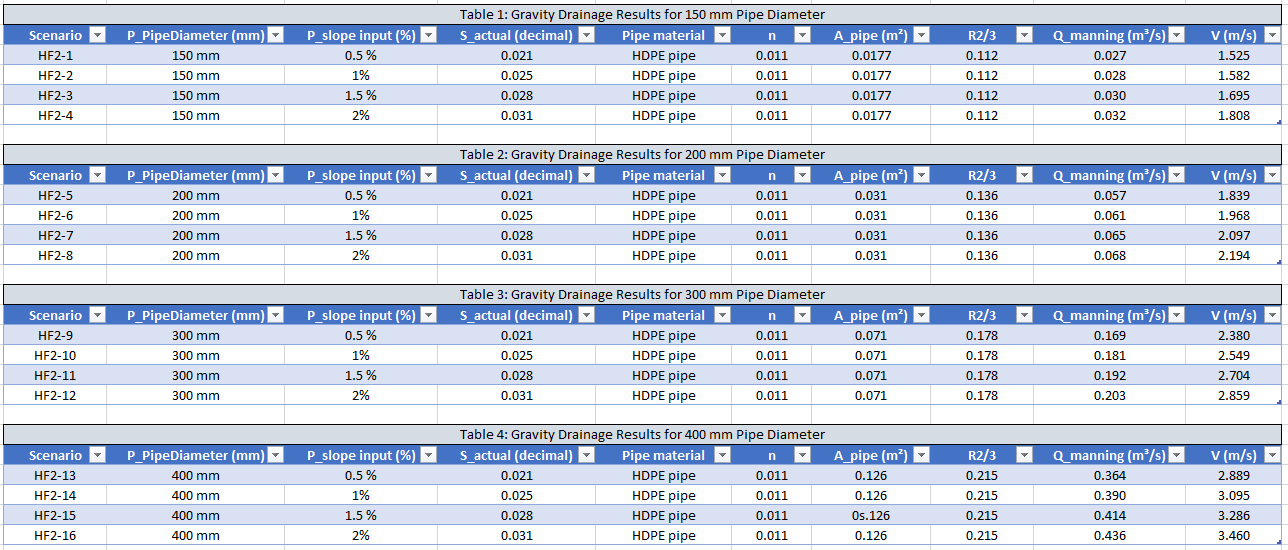
Table 1: HF2 scenario results showing Manning discharge and velocity for varying pipe diameters and slopes.
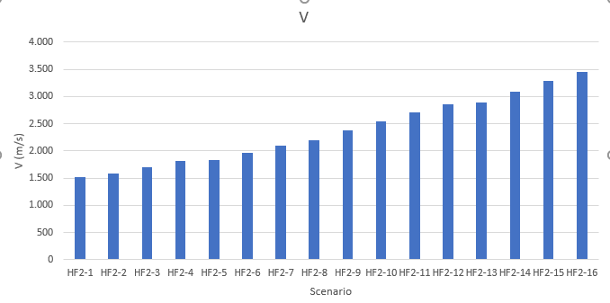
Figure 9: Flow velocity trends across HF2 diameter–slope scenarios.
Engineering use and future extension
HF2 provides engineers with a practical early-stage decision-support tool for assessing gravity drainage feasibility and relative performance without requiring detailed hydrological data. By combining a binary gravity-functionality check with comparative Manning-based capacity indicators, HF2 helps identify robust drainage configurations suitable for high-terrain and rainfall-prone sites during conceptual design. The framework is intentionally extensible: future users could incorporate rainfall demand, catchment area, sediment deposition, or maintenance and clogging logic to transition the model toward detailed design or life-cycle performance assessment, while preserving the existing parametric structure.
REFERENCES
1] Butler, David, and John W. Davies. Urban Drainage. 3rd ed., CRC Press, 2011.
2] DIN 1986-100. Drainage Systems on Private Ground – Part 100.
3] DIN EN 12056. Deutsches Institut für Normung, 2016.
Home | Individual Systems | Integration Context | Combined Ontology | Combined Parametric Model