Purpose and role in the integrated system
HF1 defines a height-based safety buffer around the retaining wall to ensure safe separation from adjacent systems in the integrated civil model. Since the wall separates the upper helipad from the lower foundation, system placement in this zone is safety-critical. Based on retaining-wall design guidance indicating an influence zone of 1.0–1.5 times the wall height [1], a conservative buffer of 2.0 H is adopted to account for uncertainty. Implemented as a binary pass/fail check, HF1 supports early-stage feasibility assessment and conservative layout decisions before detailed design.
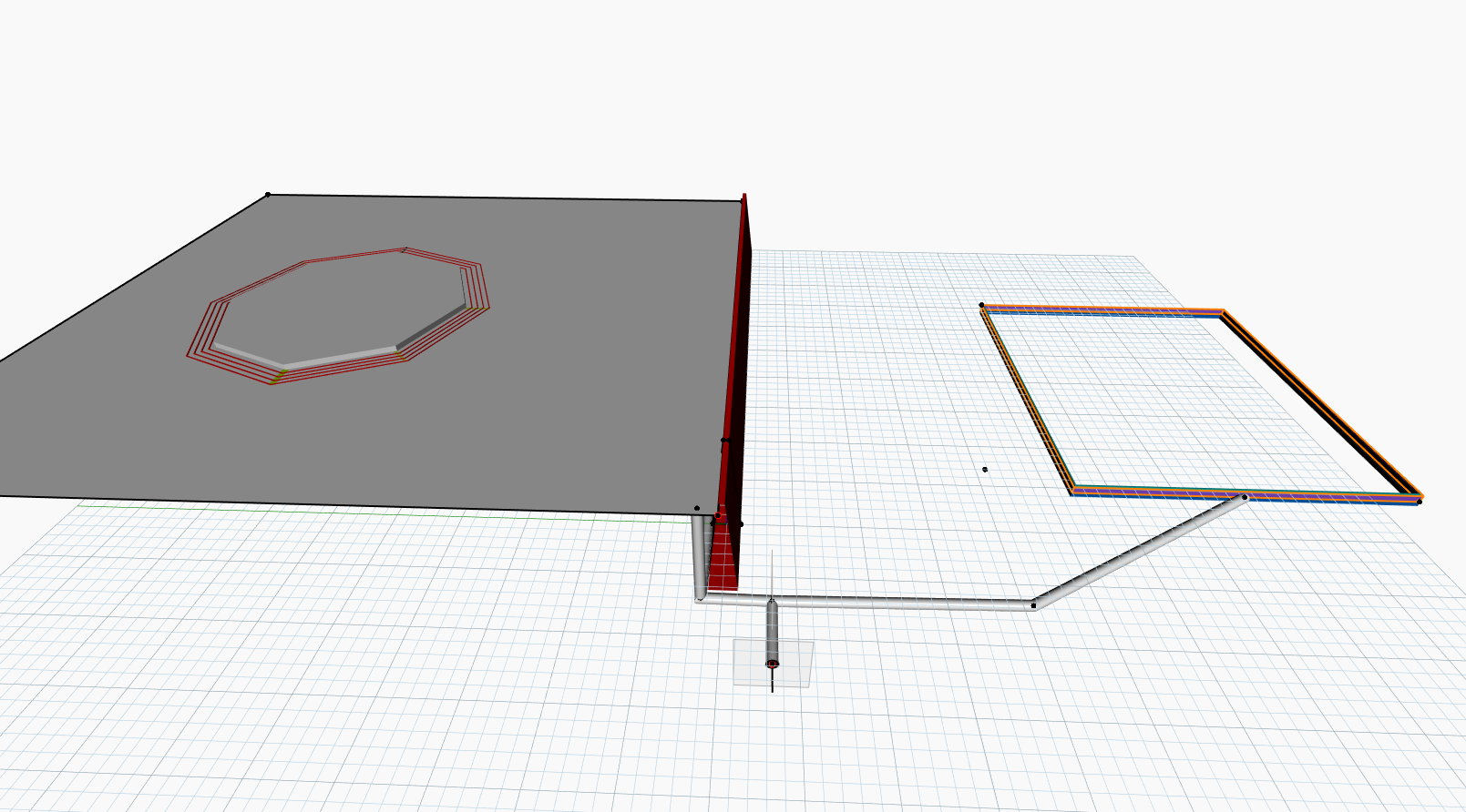
Figure 1: Spatial relationship between the retaining wall, helipad, and foundation used for HF1 safety-distance evaluation.
HF1 – Scope and modelling level
HF1 is an early-stage, reference-based safety check focused on spatial layout rather than detailed structural or geotechnical design. The retaining wall is modeled as a simplified gravity wall with fixed realistic geometry, while wall height is treated as a parametric variable within a 3–8 m [1] range representative of high-terrain conditions. HF1 does not assess bearing capacity, stability, or earth pressures; instead, it assumes competent founding conditions and verifies that the helipad and foundation lie outside the wall’s influence zone using conservative, literature-informed safety distances for early feasibility assessment.
HF1 does not perform bearing capacity or stability calculations directly. Instead, it assumes that the retaining wall is founded on competent rock or dense soil, consistent with high-terrain conditions, where allowable soil bearing capacities in excess of 600 kPa are commonly reported in geotechnical references for rock, very dense gravel, or weathered bedrock [2,3].
HF1 – Safety distance logic and parameter definition
HF1 applies a height-based safety distance rule in which the minimum required separation from the retaining wall is defined as a function of wall height, using a conservative factor of 2.0
(dmin=2H). In Dynamo, this rule is first implemented through prescriptive coordinate offsets that control the intended direction and magnitude of helipad and foundation placement relative to the wall. These offsets guide positioning but do not represent actual measured distances.
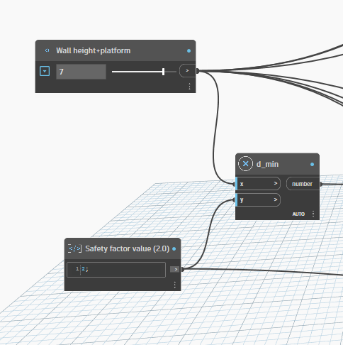
Figure 2: Dynamo implementation of the height-based safety distance rule.
True safety verification is carried out separately using geometry-based distance calculations, where the real distances between the retaining wall and adjacent systems are computed directly from the model geometry and compared to the required minimum distance using boolean checks. The outputs are clear pass/fail status indicators (e.g., OK or Too close), ensuring that any violation of the safety buffer—whether caused by parametric changes or manual adjustments—is reliably detected.
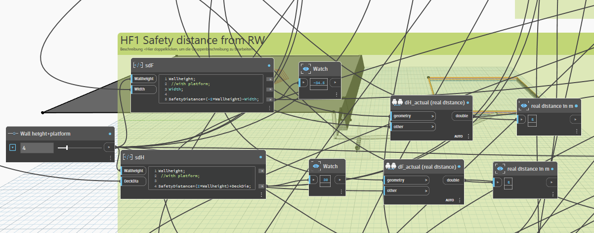
Figure 3: Geometry-based verification of required versus actual safety distances in HF1.
Results and Interpretation
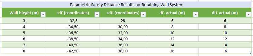
Table HF1-1: Parametric computation of the required safety distance from the retaining wall using wall height and a constant safety factor.
Table HF1-1 presents the results of the parametric safety-distance evaluation obtained by varying the retaining wall height and applying the conservative rule
(𝑑min)=2H. The results show a clear linear relationship between wall height and required safety distance, with both the prescribed offsets and the measured geometric distances increasing proportionally as wall height increases. This confirms that the HF1 logic behaves predictably and that the parametric implementation is stable and internally consistent. From a layout perspective, the results demonstrate that higher retaining walls impose progressively larger spatial constraints on adjacent systems, highlighting HF1’s value as an early-stage screening tool for assessing layout feasibility before detailed design.
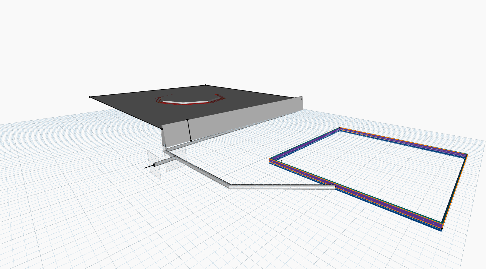
Effect of retaining wall height on spatial layout
4 m wall H
8m Wall H
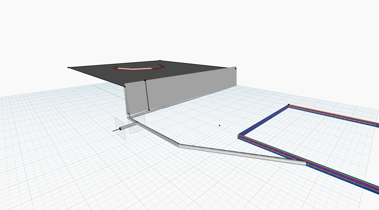
Figure 4(a & b): Comparison of system layout for retaining wall heights of 4 m and 8 m, illustrating the increase in required safety distance and associated spatial constraints under HF1.
References
1] CIRIA. C760 – Embedded Retaining Walls: Guidance for Economic Design. CIRIA, 2015.
2] Bowles, Joseph E. Foundation Analysis and Design. 5th ed., McGraw-Hill, 1996.
3] Das, Braja M. Principles of Foundation Engineering. 8th ed., Cengage Learning, 2016.
4] Federal Highway Administration (FHWA). Design and Construction of Mechanically Stabilized Earth Walls and Reinforced Soil Slopes. FHWA-NHI-10-024, U.S. Department of Transportation, 2009.
Home | Introduction | Individual Systems | Integration Context | Combined Ontology | Combined Parametric Model