The integration of the individual civil engineered systems gives rise to a set of system interfaces through which the systems interact and influence one another. This section examines the principal interfaces and the resulting interdependencies between the systems.
Building (Precast Concrete Facade System & ETICS) and Stormwater Vault System
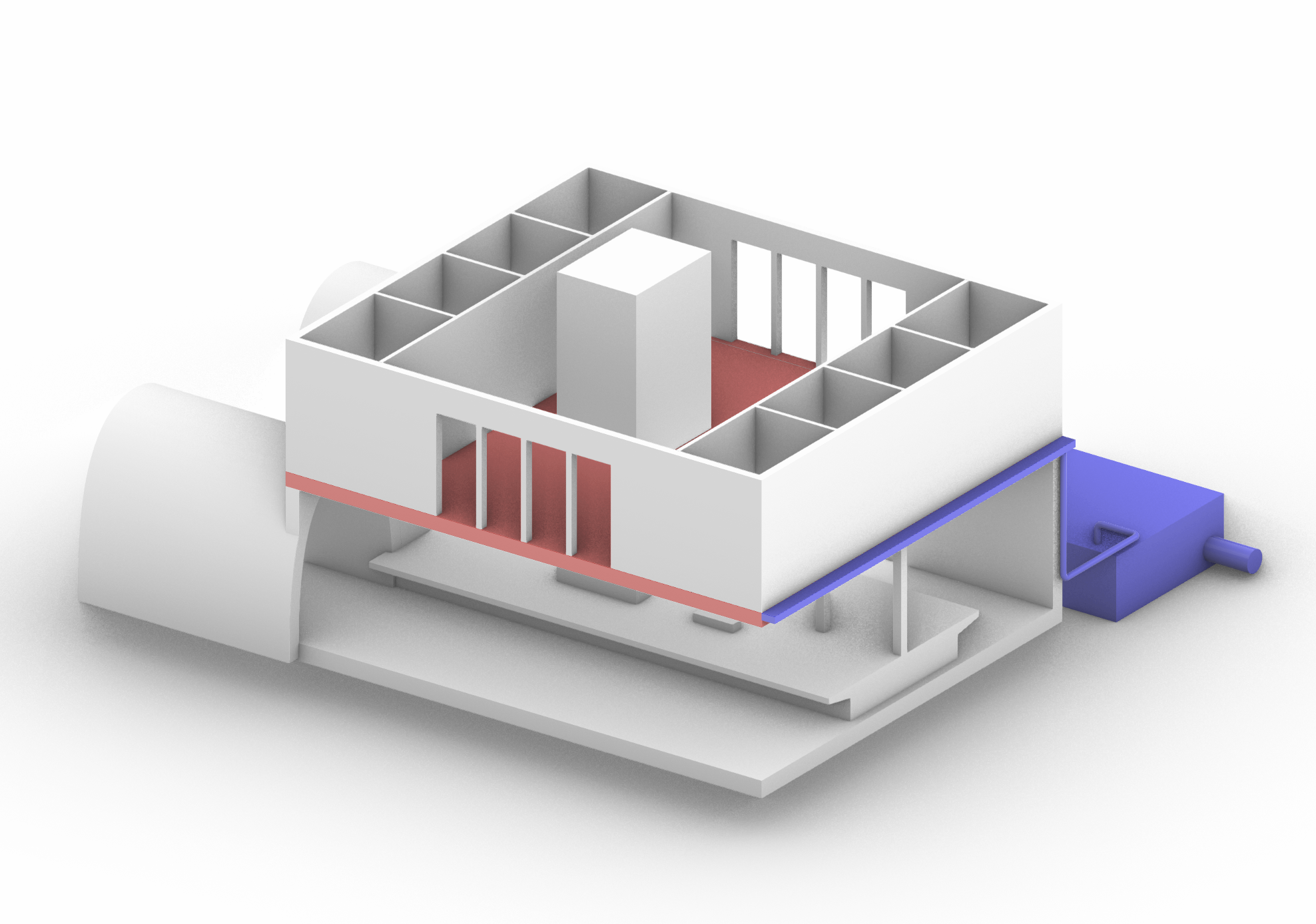
The size and footprint of the above-ground building (red) and metro station directly determine the extent of sealed surfaces that would otherwise support natural water infiltration and runoff. This creates an intrinsic relationship between the building and the stormwater vault system (blue), as increased building area leads to higher runoff volumes that must be managed through subsurface infiltration and storage solutions. Consequently, larger buildings generally require larger stormwater vault capacities. However, the required size of the stormwater vault is also strongly influenced by geographic and climatic conditions, as locations with higher precipitation intensities demand greater storage and infiltration capacity than stations situated in drier regions.
Precast Concrete Facade System and External Thermal Insulation Composite System (ETICS)
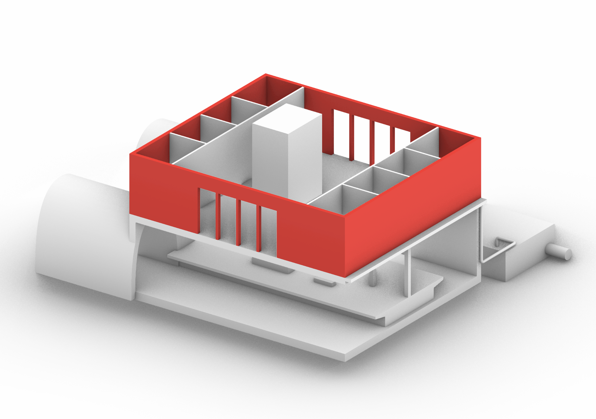
The precast concrete façade system forms the external enclosure of the building, while the ETICS constitutes its thermal envelope (red). Together, these systems govern the thermal performance of the building and directly influence its operational energy demand. Design parameters such as window-to-wall ratio and insulation thickness have an immediate impact on energy efficiency and indoor thermal conditions. The interaction between these parameters enables the exploration of trade-offs between occupant comfort and energy demand.
Building (Precast Concrete Facade System & ETICS) and Station Box
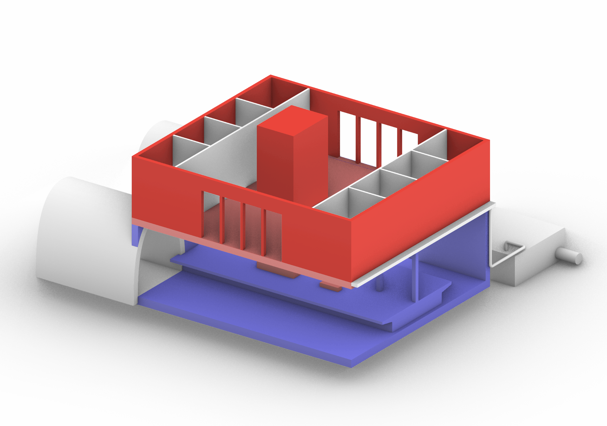
The above-ground building (red) serves as the primary entrance to the metro station (blue); therefore, the building and the station box must be spatially aligned through vertical access elements such as lifts and staircases. These access elements impose strict geometric and positional constraints, as their locations must correspond precisely with platform layouts within the station box. As the number of metro lines serving the station increases, the number of platforms, and consequently the required vertical access points also increases, further constraining the spatial configuration of both the building and the station box.
Station Box and Tunnel
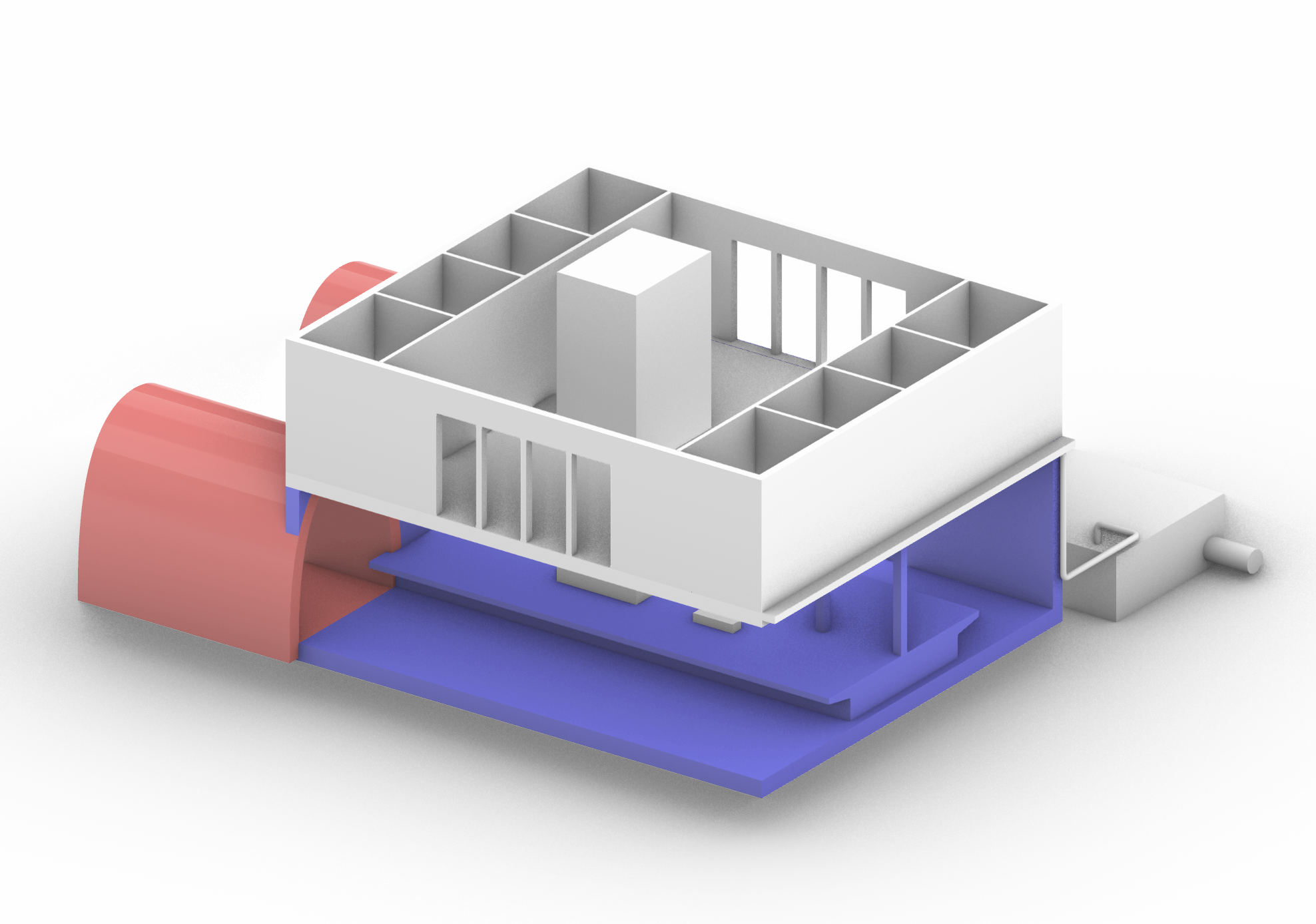
The station box (blue) and tunnel (red) constitute structurally and functionally integrated systems that together form the core transportation infrastructure of the metro station. Both accommodate train tracks and must be geometrically and operationally aligned to ensure continuity of rail operations, appropriate platform geometry, and safe passenger movement. As the number of metro lines serving the station increases, the required number of tunnels grows accordingly, directly influencing the width and overall spatial configuration of the station box.
Station Box and Stormwater Vault System
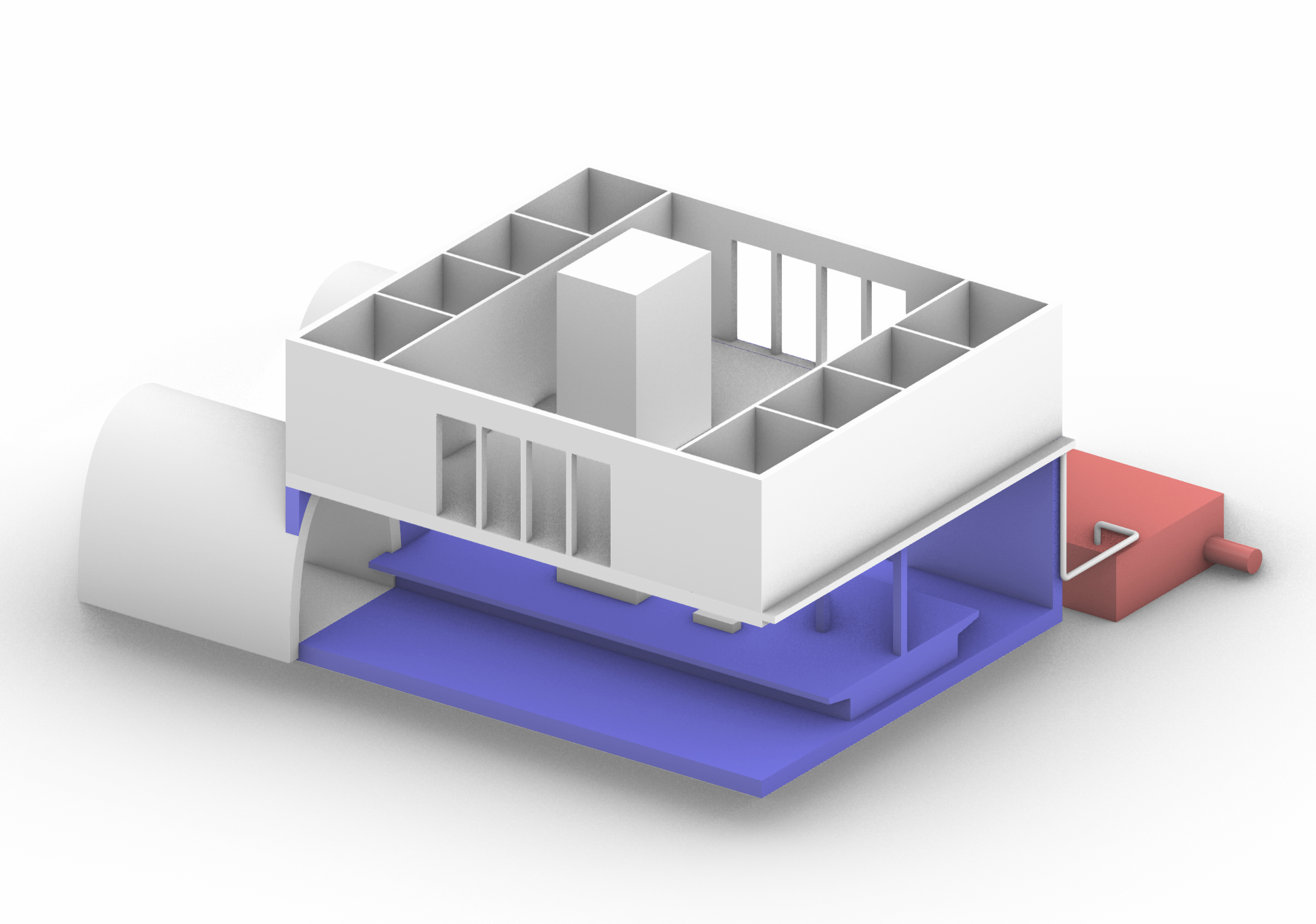
Although both systems are located underground, the station box (blue) and the stormwater vault system (red) must maintain a minimum separation distance due to geotechnical and structural considerations, including load transfer, soil stability, and groundwater behaviour. This requirement imposes spatial constraints on the placement of stormwater infrastructure relative to the station box, thereby directly influencing the underground layout of the integrated system.