Integration Context
This project develops an integrated system for constructing a new nuclear containment facility on a constrained site while meeting a municipal tender requirement for minimum CO₂ emissions. The site is defined by two fixed conditions: a river and an abandoned historical masonry building. The containment facility is placed on the clear land beyond the river to support isolation and safety, while the historical building is retained and renovated to serve as a maintenance and service facility. Because the Design Bid Build tender is awarded primarily on environmental performance, our integration focuses on how parametric changes in one subsystem propagate into embodied CO₂ and cost across the rest of the system.
A key integration challenge is that the nuclear facility cannot function as a standalone object. It requires a reliable access corridor for construction, operation, deliveries, and emergency response. This makes the road (pavement) + steel truss bridge central to the system because they physically connect the containment site to the historical building and the broader transport network. In parallel, the historical building cannot be reused without structural intervention: it needs a new roof structure and must satisfy the municipality’s requirement of a minimum 10% green roof coverage, which adds dead load and can trigger strengthening needs.
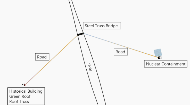
Fig.1
To address the tender requirement, the integrated system is evaluated through two coupled value drivers: CO₂ performance (municipality objective) and economic viability (project objective). From the municipality’s perspective, the best proposal achieves the lowest combined CO₂ footprint while still providing a safe, functional facility and refurbished historic asset. From the developer’s perspective, profitability is determined by lease income from the containment facility and the renovated building compared with construction and material costs for the containment structure, bridge, pavement works, and the historic building retrofit.
Integrated parametric design decisions
Based on our current model, the integration is driven by the following design-change inputs in fig.2.
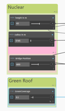
Fig. 2
These are the parameters that actively change the geometry and therefore shift CO₂ and cost:
1) Access (Bridge + Pavement)
The bridge length (directly linked to the position of the bridge) is a primary integration driver. Changing bridge position/length changes:
- the amount of steel truss structure required (mass, fabrication),
- the span requirement over the river (and related bridge complexity),
- and it directly sets the length of the pavement section (since the pavement length is defined by the bridge position/length in our workflow).
This means bridge placement is not only a layout choice, but a cost/CO₂ lever that also affects the road system through derived lengths.
2) Containment structure geometry (Concrete wall)
Instead of using reactor size as the main variable, the containment building is parametrized through its wall geometry:
- radius of the concrete wall
Its size is controlled by a radius parameter (with a fixed height of 45 m and a minimum radius range 17–18 m required by the project constraints).
These geometry changes scale the concrete quantity and therefore directly affect:
- embodied CO₂ (cement-intensive materials),
- construction cost (volume-driven),
3) Historical building roof retrofit (Green roof + timber structure)
The roof retrofit is modeled as a coupled system rather than a single “green roof” slider. The key changing inputs are:
Green Roof System
- deck thickness
- substrate thickness
- green roof coverage % (including the minimum 10% requirement)
These control the added dead load and therefore influence structural demand.
What the integration structure enables
Together, these elements form a single integrated system because none of the subsystems can be optimized independently. For example, moving the bridge to reduce span length may reduce steel and cost but increase (or decrease) the pavement length and associated emissions. Increasing green roof coverage improves tender alignment but raises roof dead load, which can push the timber truss system and masonry bays toward strengthening measures. Increasing containment wall radius or height increases concrete volume and embodied CO₂, which can dominate the project footprint unless offset by reductions elsewhere. The final design is therefore selected by comparing combined system outcomes across CO₂ and cost, with the primary objective of winning the tender on emissions while keeping the project internally viable.
By combining the ontology structure with the Dynamo computations, the project becomes transparent and reproducible:
- Ontology defines: systems, parameters, outputs, constraints, and dependencies (what exists and how it relates).
- Dynamo computes: quantities, embodied CO₂ (A1–A3), costs, and ROI across design variants.
This makes it easy to explain why a configuration performs well (or fails), and it makes it straightforward to extend the model with additional requirements or parameters if the group decides to add them.