Design Parameters
The integrated system is controlled through a set of design parameters that define the geometry and structural behavior of each component. These parameters are used within the parametric model to explore different design configurations and to evaluate their influence on system-level performance.
Rather than assigning parameters in isolation, the selected design variables reflect the interaction between the structural components and the integration context. This approach allows consistent modification of the system while maintaining its overall configuration.
Table 2. Design parameters within the integrated system
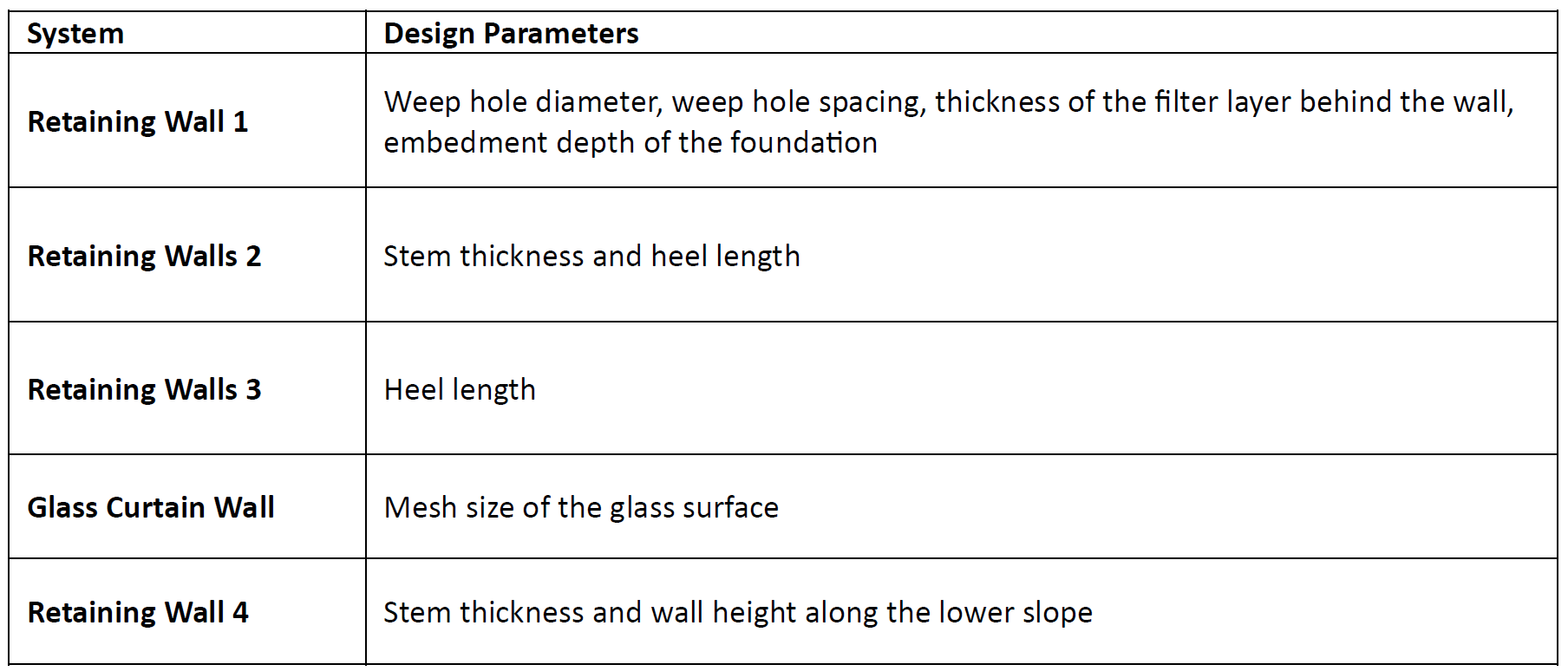
Although these design parameters may appear to be independent from one another, they collectively influence the overall system behavior. The impact of variations in these design parameters on the system will be explained in detail in the Performance Indicators section.
Performance Indicators
To evaluate the effect of different design configurations, the system is assessed using safety oriented Performance Indicators. Each PI is directly linked to the integration context and focuses on how design decisions influence the safety and serviceability of the overall system.
Table 3. Performance Indicators (PIs) and controlling design parameters
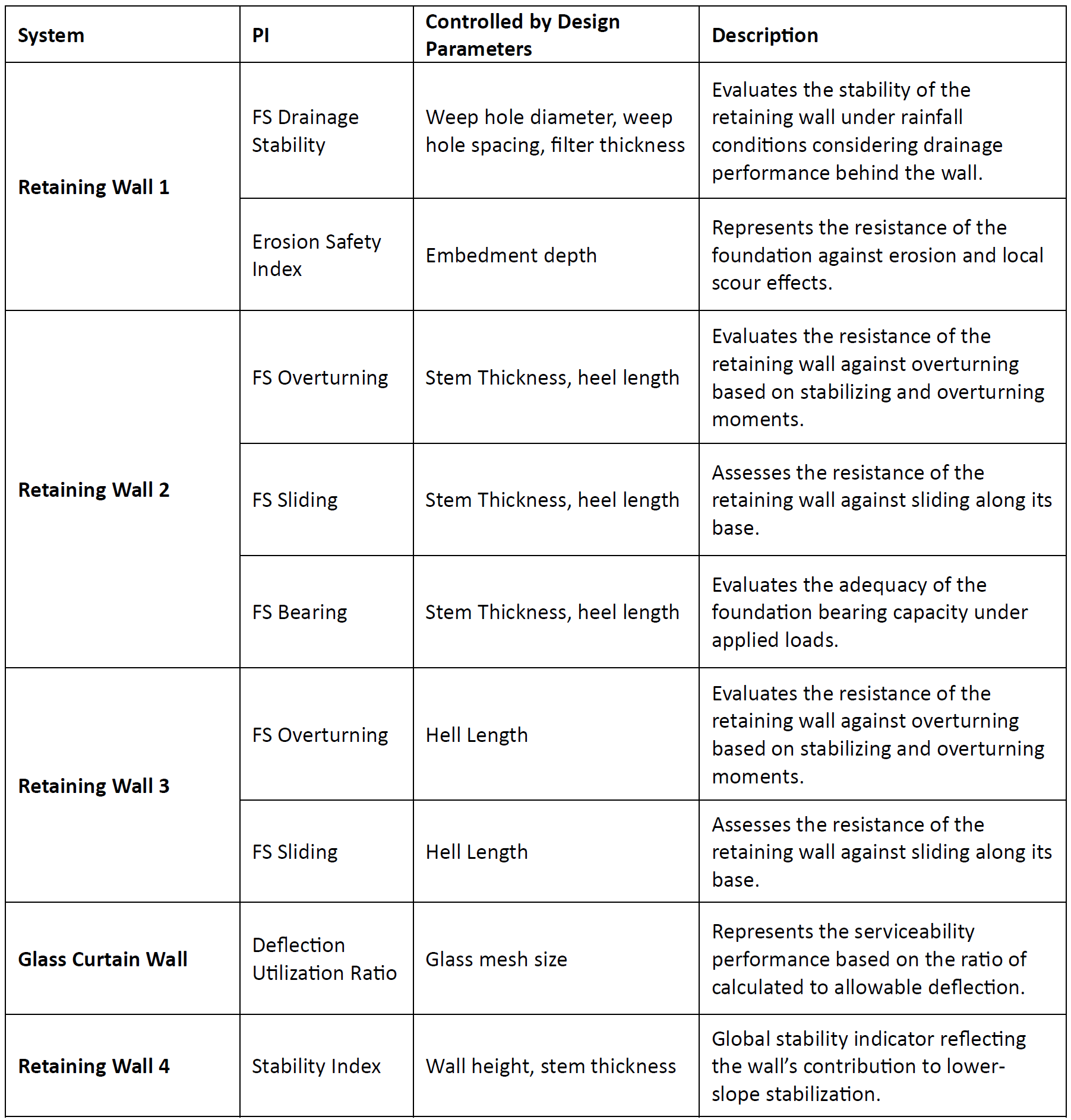
Although Retaining Wall 2, Retaining Wall 3, and the Glass Curtain Wall are parametrized together and show a coordinated geometric behavior within the system, each component in the integration framework has its own specific PIs, as presented in the table. At first glance, this may give the impression that the system is not fully integrated. However, reducing the entire system to a single PI would be misleading and overly simplified from an engineering perspective.
For this reason, the system is evaluated by considering how the performance indicators of individual components influence each other at the system level.
Retaining Wall 1 is evaluated using drainage related stability and erosion safety indicators. If these indicators show poor performance and the wall cannot provide sufficient structural safety, the first impact would occur in the facility zone located below. This would affect the functionality of the site as a whole and could also negatively influence the structural behavior of Retaining Wall 2.
Retaining Wall 2 is evaluated using safety factors against overturning, sliding, and bearing failure. If any of these indicators fall below acceptable limits, the structural safety of the wall would be at risk. In such a case, the archaeological area, which is the main element of the system, could be damaged. In addition, the glass curtain wall supported by this retaining wall could fail, potentially creating serious safety risks if visitors are present. The facility zone behind the wall, including parking and service structures, could also be adversely affected.
A similar situation applies to Retaining Wall 3. A sliding related performance issue could cause horizontal movement along the archaeological boundary, leading to damage to the site and disruption of the overall system behavior.
For the glass curtain wall, the deflection utilization ratio reflects its serviceability performance. If deflection values exceed acceptable limits, glass panels may crack or fail. This would not only pose a direct risk to visitors but could also restrict access to the archaeological area and lead to partial or full closure of the system.
Finally, Retaining Wall 4, located at the lowest elevation, acts as a stabilizing element for the overall terrain. A stability issue at this level could trigger local soil movements and cracking in upper facility areas, indirectly affecting the performance and safety of the entire integrated system.
In summary, while PIs are defined at the component level, their implications extend beyond individual elements. Performance issues in one part of the system may propagate through other components, highlighting the importance of evaluating the design as an integrated system rather than as isolated elements.
System Level Design Alternatives
To understand how different design ideas affect the integrated system, three design scenarios are defined. All scenarios are based on the same system configuration, consisting of four retaining walls and a glass curtain wall. What changes between the scenarios is not a single element, but the way design parameters are adjusted across the system.
The first scenario represents a balanced reference case. The other two scenarios explore how the system behaves when the design focus shifts either towards rainfall and slope conditions or towards visitor safety and heritage protection.
Before discussing the different system design alternatives, the parameters that are assumed to be constant in all system designs are summarized in Table 4 and Table 5.
Table 4 – Fixed System Geometry Parameters
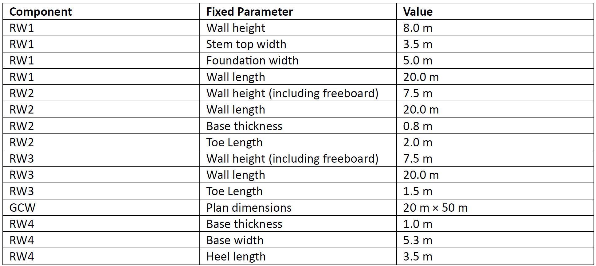
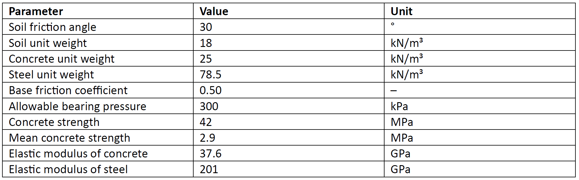
Table 5 – Fixed Material and Soil Parameters