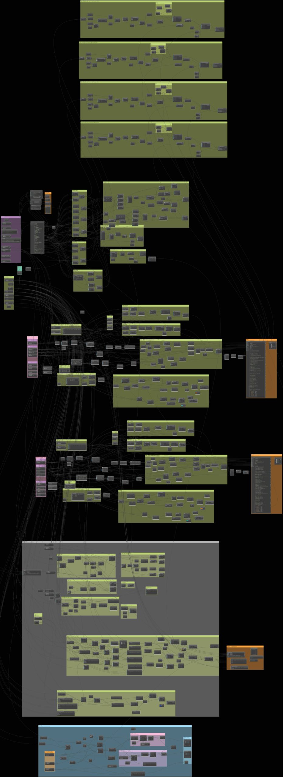
Model Parameter Definition
The parametric model is implemented using Dynamo and forms the core environment for integrating and exploring the interactions between the individual subsystems. The model combines all civil engineered subsystems into a single parametric framework, enabling the evaluation of how changes within one subsystem affect the overall system performance. The development of the parametric model began with the identification and definition of subsystem-specific constraints. For each subsystem, two categories of parameters were distinguished:
- constraint parameters, which must be satisfied for the subsystem to function correctly within the integrated system, and
- design variables (key parameters), which are intentionally varied to explore alternative design configurations and represent the key parameters of the model.
The selection of key parameters was guided by the defined high-performance criteria as well as by the physical, geometric, and functional constraints inherent to each subsystem.
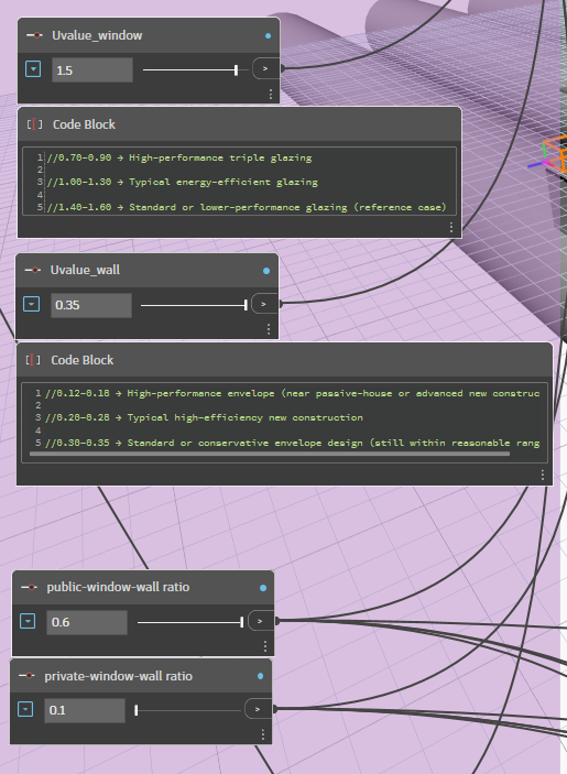
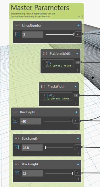
Within this framework, the building envelope, underground transportation system, and stormwater infrastructure are represented through a set of design variables and constraints. The table below offers an overview of the constraint parameter and design variables within this model. More detailed information on each model parameter can be found at the subpage of each subsystem.
| System | Constraint Parameter | Design Variable |
| Metro Station | Number of Train Lines | |
| Station Box | Box Width | |
| Platform Geometry and Position | ||
| Box Depth | ||
| Box Height | ||
| Box Length | ||
| Tunnel | Distance between Tunnels | |
| Tunnel Width | ||
| Tunnel Depth | ||
| Precast Concrete Facade System | Module Width | |
| Insulation Material and Dimension (U-Value) | ||
| Window Glazing and Construction (U-Value) | ||
| Window-to-Wall Ratio (WWR) | ||
| External Thermal Insulation Composite System (ETICS) | covered by the model parameters of precast concrete facade system | |
| Storm Water Vault | Position | |
| Storm Water Vault Width | ||
A Miro board was used as the primary workspace and contains additional information on the rationale behind the selected parameters and constraints. The link to the bird can be found at the bottom of the page.
Measured Outputs
Through the variation of the previously defined parameters, the model generates a set of outputs that support evaluation and decision-making. These outputs are directly aligned with the two high-performance criteria defined for the project: capacity and operational energy efficiency.
Capacity
- Passenger Capacity [pax]
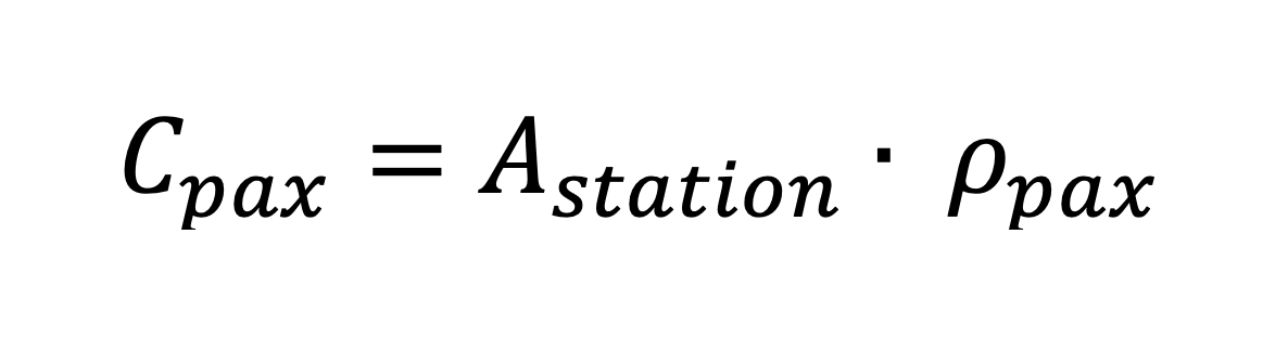
Cpax = passenger capacity [pax]
Astation = available floor area of the station [m2]
ρpax = passenger density [pax/m2], assumed as 4 pax/m²
Passenger capacity is computed based on the available floor area within the station box in combination with the assumed passenger density, as defined under the station box length parameter. This output provides an estimate of how many passengers can be accommodated and transported within the station at a given time. - Public Using Area [m²]

Apublic = public using area [m3]
Lbldg = building length [m]
Wbldg = building width [m]
Wservice = width of service band [m]
The public-use area is calculated at the plan level and represents the net floor area available for public use after deducting service, circulation, and restricted zones. This output reflects the building’s capacity to accommodate public and social activities. It provides insight into the spatial efficiency of the building in relation to its overall proportions and zoning strategy and is directly influenced by variations in building length and width. - Stormwater Vault Capacity [m3/m2]
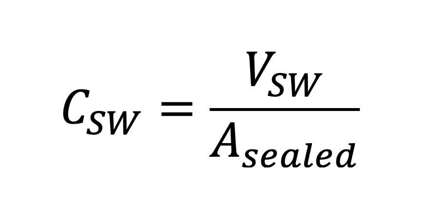
CSW = stormwater vault capacity per sealed surface area [m3/m2]
VSW = total stormwater vault storage volume [m3]
Asealed = sealed surface area associated with the station and building footprint [m2]
Stormwater vault performance is evaluated through the storage volume provided relative to the extent of sealed surface area. This output indicates how effectively the stormwater vault system mitigates runoff and supports groundwater infiltration for different station configurations.
Operational Energy Efficiency
- Average U-Value of Building Envelope [W/m²·K]
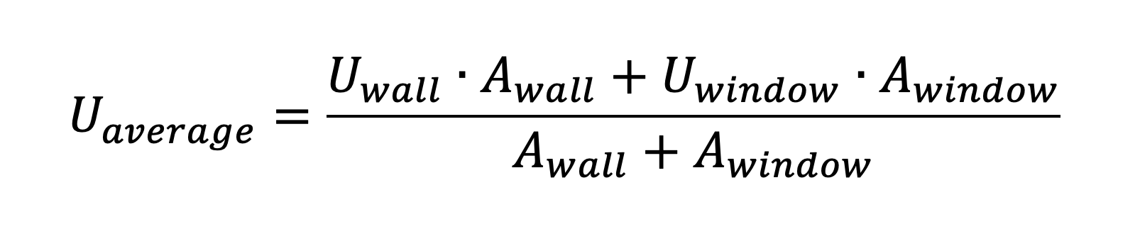
Uaverage = average U-value of the building envelope [W/m²·K]
Uwall = U-value of the opaque wall [W/m²·K]
Uwindow = U-value of the window [W/m²·K]
Awall = surface area of opaque wall [m²]
Awindow = surface area of window [m²]
The average U-value of the building envelope is evaluated at the building scale using an area-weighted approach. The building is defined by a rectangular plan, in which the longer façades (length) are assigned to private functions and the shorter façades (width) to public functions. Different window-to-wall ratios (WWR) are therefore applied to private and public sides to reflect their distinct functional and spatial requirements. Based on the plan dimensions and a uniform floor height, the external envelope is subdivided into window and opaque wall components. The overall U-value of the building envelope is then calculated by weighting the U-values of these components by their respective surface areas. This aggregated U-value captures the combined effects of façade and ETICS-related design variables and provides a direct indicator of the thermal performance of the envelope and its influence on heating and cooling energy demand. - Ventilated Air Volume within the Station Box [m³]
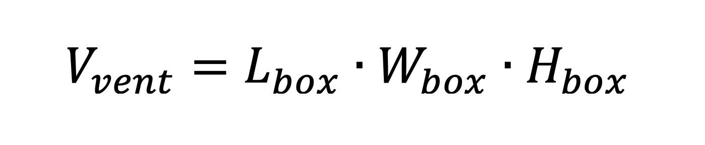
Vvent = ventilated air volume within the station box [m3]
Lbox = station box length [m]
Wbox = station box width [m]
Hbox = station box height [m]
The volume of air that must be ventilated within the station box is used as a proxy for ventilation-related operational energy demand. This output enables comparison between different station sizes and configurations, illustrating how increases in station volume affect energy demand and associated operational costs. - Ratio of Private Area to Ventilate [m2/m3]
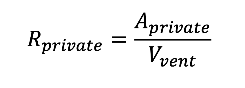
Rprivate = ratio of private (revenue-generating) area to ventilated volume [m2/m3]
Aprivate = total private area, including above-ground retail space and underground business zones [m2]
Vvent = total ventilated air volume [m3]
The ratio of private area to ventilated volume is used to capture the balance between revenue-generating space and ventilation-related operational demand. By relating monetizable floor area to the volume of air that must be mechanically conditioned, the metric highlights how geometric decisions affect the economic efficiency of the station. A higher ratio indicates that a given ventilation demand is supported by a larger private area, while a lower ratio reveals increasing operational burden per unit of revenue-generating space.