1 Background Research
Offshore wind turbine (OWT) structures have become one of the key directions in recent renewable energy development. Their supporting structures must remain safe and stable under extreme conditions such as strong winds, high waves, and corrosive seawater. Nevertheless, deficiencies still exist in current design codes, load combination methodologies, and cost optimization strategies [1]. Therefore, this study selects the OWT Tower as the research object. Following the process proposed by Noy and McGuinness [2], after determining the research domain and scope, we should define the classes and class hierarchy, and define the probability of class-slots
This study focuses on the physical composition, material, and uses of the tower, from the foundation to the nacelle connection. The goal is to establish a systematic knowledge framework to assist structural engineers in design, analysis, and maintenance decision-making. Through constructing the ontology model of the OWT tower, the physical components, main materials, and functions can be systematically described. This enables the formation of a parametric model that helps designers select suitable tower configurations and material schemes under different marine conditions and engineering constraints. Furthermore, it provides informational support for subsequent maintenance planning, cable routing, and condition monitoring.
2 Main Categories
To facilitate an intuitive understanding of the subject and its compositional structure, Fig.1(a) presents a simplified system schematic of an OWT tower.
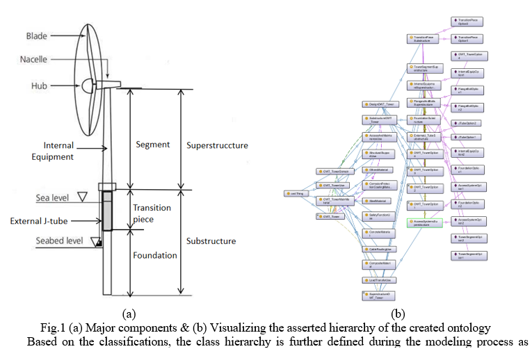
Based on the classifications, the class hierarchy is further defined during the modeling process as follows:
Physical Components [1]
- Substructure
- Foundation
- Transition piece
- External J-tube
- Superstructure
- Tower segment
- Flanges and bolts
- Access systems
- Internal equipment
Main material [3]
- Steel
- Concrete
- Composite material
- Corrosion protection coating
Uses(functions) [4,5]
- Structural support
- Load transfer
- Access and maintenance
- Cable routing
- Safety function
3 Ontology Modeling Process
This chapter introduces the specific ontology modeling process in the Protégé environment. For clarity, Fig.1(b) presents the visualization of the finalized ontology structure. A summary of the logical axioms applied in this model is provided in Table 1. And Fig.2-7 shows part of the model process.
Table 1: Logical Axioms
| Class Hierarchy | DesignOWT_Tower ⊑ OWT_Tower |
| OWT_TowerOption1 ⊑ DesignOWT_Tower | |
| SubstructureOWT_Tower ⊑ OWT_TowerDomain | |
| ExternalJ_TubeSubstructure ⊑ SubstructureOWT_Tower | |
| CompositeMaterial ⊑ OWT_TowerMainMaterial | |
| AccessAndMaintenanceUse ⊑ OWT_TowerUse | |
| CableRoutingUse ⊑ OWT_TowerUse | |
| Object Properties | hasSubstructure ⊑ hasComponent |
| isSubstructureOf ⊑ isComponentOf | |
| hasComponent ≡ isComponentOf— | |
| hasSubstructure ≡ isSubstructureOf— | |
| Object Property Characteristics | ∃ hasSubstructure.⊤ ⊑ OWT_Tower |
| ⊤ ⊑ ∀ hasSubstructure.SubstructureOWT_Tower | |
| ∃ isSubstructureOf.⊤ ⊑ SubstructureOWT_Tower | |
| ⊤ ⊑ ∀ isSubstructureOf.OWT_Tower | |
| ∃ isMainMaterialOf.⊤ ⊑ OWT_TowerMainMaterial | |
| ⊤ ⊑ ∀ isMainMaterialOf.OWT_Tower | |
| ∃ isUseOf.⊤ ⊑ OWT_TowerUse | |
| ⊤ ⊑ ∀ isUseOf.OWT_Tower | |
| Properties Restriction | OWT_Tower ⊑ (∃ hasSubstructure.SubstructureOWT_Tower) ⊓ (∃ hasSuperstructure.SuperstructureOWT_Tower) ⊓ (∃ hasMainMaterial.OWT_TowerMainMaterial) |
| Individaul | TransitionPieceSubstructure(TransitionPieceOption1) |
| Data Property | hasDiameter(TransitionPieceOption1,5.5) |
| Class Equivalences | TransitionPieceSubstructure≡ {TransitionPieceOption1} ⊔ {TransitionPieceOption2} |
| Design Option(OWT_TowerOption1) | OWT_TowerOption1 ⊑ (∃ hasAccessSystems.{AccessSystemOption1}) ⊓ (∃ hasExternalJ_Tube.{JTubeOption1}) ⊓ (∃ hasFlangesAndBolts.{FlangeBoltOption1}) ⊓ (∃ hasFoundation.{FoundationOption1}) ⊓ (∃ hasInternalEquipment.{InternalEuipOption1}) ⊓ (∃ hasTowerSegment.{TowerSegmentOption1}) ⊓ (∃ hasTransitionPiece.{TransitionPieceOption1}) ⊓ (∃ hasSubstructure.ExternalJ_TubeSubstructure) ⊓ (∃ hasSubstructure.FoundationSubstructure) ⊓ (∃ hasSubstructure.TransitionPieceSubstructure) ⊓ (∃ hasSuperstructure.AccessSystemsSuperstructure) ⊓ (∃ hasSuperstructure.FlangesAndBoltsSuperstructure) ⊓ (∃ hasSuperstructure.InternalEquipmentSuperstructure) ⊓ (∃ hasSuperstructure.TowerSegmentSuperstructure) |
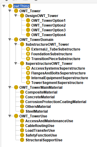
3.1 Class Hierarchy Modeling
Based on the classification discussed in Chapter 2, a class hierarchy was constructed in the Protégé environment.
3.2 Object Properties and Semantic Relations Modeling
Object properties were defined to capture semantic relationships between classes
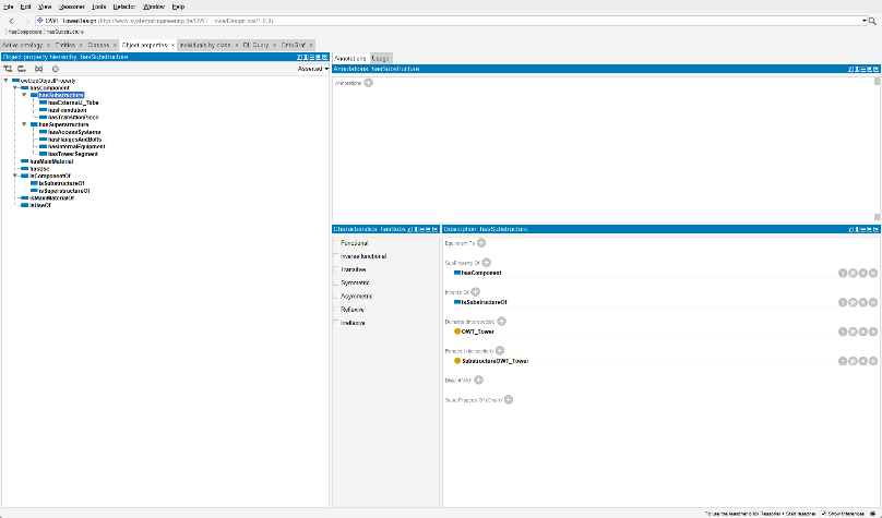
Fig. 3
All “has–is” properties were defined with inverse relationships (InverseOf) in Protégé to ensure bidirectional semantic consistency.
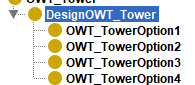
3.3 Create design options for the OWT Tower
Four design variants of the OWT Tower were defined, distinguished through different data properties to reflect their specific differences.
3.4 Creation of individuals and defining the data properties
At the individual level, four tower design options were instantiated (Fig. 5). The first option, OWT_TowerOption1, is associated with minimum parameter values, while OWT_TowerOption4 corresponds to maximum parameter values; the other two options take intermediate values. These parameters are derived from [6] and reference structural specifications of typical 5–8 MW wind turbine towers [7]. Geometric and structural parameters are expressed using data properties, for example, hasDiameter (TransitionPieceOption1, Fig. 6). This instantiation approach demonstrates the model’s parameterization and inferential capability.
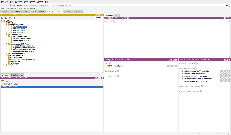
Fig: 5
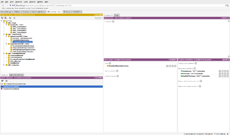
Fig: 6
3.5 Example of Design Option Modelling
Taking OWT_TowerOption1 as an example, the model represents a complete tower configuration through a series of object properties
The design option includes multiple substructure and superstructure components:
- Substructure components include: FoundationOption1, ExternalJ_TubeOption1, and TransitionPieceOption1
- Superstructure components include: AccessSystemOption1, InternalEquipOption1, FlangeBoltOption1 and TowerSegmentOption1, among others。
By combining multiple hasSubstructure and hasSuperstructure relationships, the model fully captures the composition logic of the complex structure, which can be recognized and reasoned by Pellet.
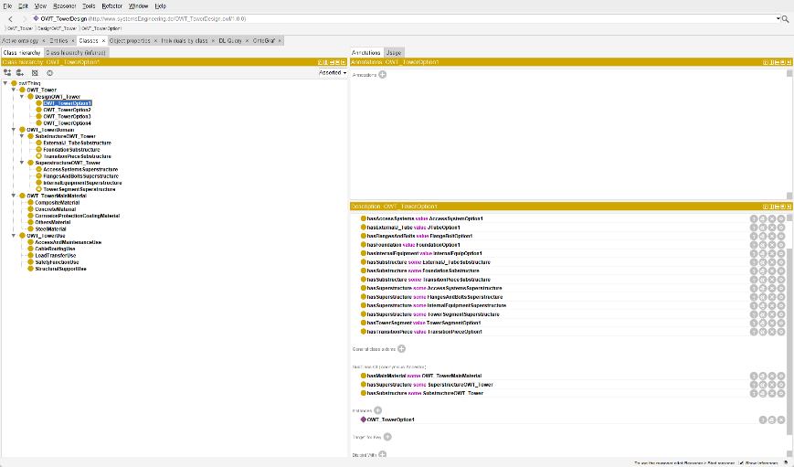
Fig: 7
4 Engineering Example
4.1 Update the Layout of Internal Equipment in the Tower
Scenario: With the increase in wind turbine capacity, more electrical equipment (such as inverters, cables, and monitoring systems) needs to be installed inside the tower, which increases the load and spatial complexity inside the tower. If not properly arranged, it may lead to local stress concentration, difficulty in maintenance, or poor access.
Use Case: Using ontology classes such as InternalEquipmentSuperstructure, CableRoutingUse, and AccessAndMaintenanceUse, designers can systematically organize the relationships between equipment, support structures, and maintenance channels. By utilizing the parameterized model generated by the ontology, spatial conflicts can be automatically detected, the impact of load distribution on the structure can be analyzed, and the internal layout of the tower can be optimized to achieve a balance between structural performance and functional layout.
4.2 Selection and Evaluation of Tower Corrosion Protection System
Scenario: A certain offshore wind turbine tower has experienced coating aging in a corrosive marine environment, and protective materials need to be re-selected and their durability evaluated.
Use Case: Engineers can compare the performance of different coatings and their compatibility with other components, such as Flanges and Bolts, through the Corrosion Protection Coating Material in the body, and select appropriate materials that meet the requirements. This enables the establishment of a parameterized model for protective system design.
4.3 Selection and adaptation of multiple types of Foundation
Scenario: The geological conditions in a certain sea area are complex, including soft soil layers and rock foundations in different regions. If a single foundation form is adopted uniformly, some tower structures may experience excessive settlement or high construction costs. Therefore, it is necessary to flexibly select the appropriate type of foundation structure based on geological characteristics.
Use Case: Through the FoundationSubstructure class in the ontology and its association with SubstructureOWTtower, engineers can evaluate the applicability of different foundation forms (such as Monopile, Gravity Based). Combining geological data and water depth, a parameterized foundation tower model can be generated to automatically analyze the bearing capacity and stability under different conditions and provide a quantitative basis for optimization design.
5 Conclusion
Based on the ontology modeling approach, this work systematically describes the structural composition, primary materials, and functional purposes of OWT towers. The constructed ontology model formalizes the logical relationships of tower structures at the semantic level, providing a knowledge base to support structural optimization, material selection, and maintenance management.
Furthermore, the ontology model is validated for consistency and classification reasoning in the Protégé environment using Pellet. It can automatically identify component relationships, material compatibility, and conflicts in functional constraints, thereby ensuring semantic correctness and logical completeness.
The results indicate that the Protégé-based OWT Tower ontology not only enables intelligent reasoning of structure–function relationships but can also be integrated with parametric design and digital twin systems, providing knowledge-based support for the intelligent design and operational decision-making of future offshore wind structures.
Reference
[1] Arshad, M., & O’Kelly, B. C. (2013). Offshore wind-turbine structures: a review. Proceedings of the Institution of Civil Engineers-Energy, 166(4), 139-152.
[2] Noy, N. F., & McGuinness, D. L. (2001). Ontology development 101: A guide to creating your first ontology.
[3] Chen, J., & Kim, M. H. (2021). Review of recent offshore wind turbine research and optimization methodologies in their design. Journal of Marine Science and Engineering, 10(1), 28.
[4] Ribeiro, J. A., Ribeiro, B. A., Pimenta, F., Tavares, S. M., Zhang, J., & Ahmed, F. (2025). Offshore wind turbine tower design and optimization: A review and AI-driven future directions. Applied Energy, 397, 126294.
[5] Jiang, Z. (2021). Installation of offshore wind turbines: A technical review. Renewable and Sustainable Energy Reviews, 139, 110576.
[6] Musial, W., Heimiller, D., Beiter, P., Scott, G., & Draxl, C. (2016). Offshore wind energy resource assessment for the United States. National Renewable Energy Laboratory.[7] Jonkman, J., Butterfield, S., Musial, W., & Scott, G. (2009). Definition of a 5-MW reference wind turbine for offshore system development (No. NREL/TP-500-38060). National Renewable Energy Lab.(NREL), Golden, CO (United States).