This page documents the combined ontology developed for system-level representation of the integrated infrastructure model.
Purpose Of the Ontology
The combined ontology provides a production-grade semantic structure for system-level integration, with clear responsibility boundaries and non-duplicative knowledge representation. Rather than being exhaustive, it prioritizes explicit relationships and clean system coordination, enabling consistent reasoning and future extensions—such as BIM integration, cost modeling, and parametric binding—without restructuring.
SCOPE AND BOUNDARY
The ontology represents systems, subsystems, and components together with their relationships and selected parameters required for early-stage coordination of the integrated infrastructure model. Detailed structural design, geotechnical modeling, hydraulic simulation, and regulatory verification are outside the current scope, and any numerical values are representative assumptions rather than validated engineering results. The ontology is tool-independent and may be extended or linked to BIM, cost, or parametric environments such as Dynamo in future work.
Intended Use and Intended Users
The combined ontology is intended for use in exploratory and comparative workflows where multiple infrastructure systems must be reasoned about consistently within a shared model, particularly during conceptual layout development and design iteration.
The ontology is intended for infrastructure engineers, system designers, and researchers involved in early conceptual studies, as well as for integration with parametric and BIM-based workflows that require explicit system relationships.
Integration and Modeling Strategy
When infrastructure systems are developed independently, their interactions often remain implicit, leading to duplicated information, conflicting parameter ownership, and unclear responsibility boundaries. The combined ontology addresses this by making system interactions, constraints, and dependencies explicit, ensuring consistent and unambiguous integration.
Key Integration Challenges
- Managing shared concepts across multiple system levels
Integrating multiple infrastructure systems required handling concepts that naturally appear at different abstraction levels, creating a risk of redundancy and unclear ownership if not carefully controlled. - Representing interdependencies without introducing analytical complexity
The systems exhibit clear interactions and constraints, but capturing these relationships without turning the ontology into a numerical analysis or simulation model posed a significant abstraction challenge. - Harmonizing systems developed under different initial assumptions
The individual systems were originally defined in different contexts and underwent re-scoping during integration, requiring alignment within a single semantic framework while preserving internal consistency. - Maintaining extensibility without over-constraining the model
The ontology needed to remain adaptable to future extensions and workflows while avoiding premature commitment to specific tools, methods, or design decisions.
Modeling Strategy
Following the combined top–down and bottom–up approach described by Noy & McGuinness in Ontology Development 101, the ontology was structured by first defining system-level concepts and then refining them through relationships and component-level detail. This approach preserves a clear system organization while enabling consistent representation of physical dependencies and interactions. At the top level, the ontology distinguishes between primary infrastructure systems and supporting structures, connected through explicit system–subsystem relationships, as illustrated in the OntoGraf view below.
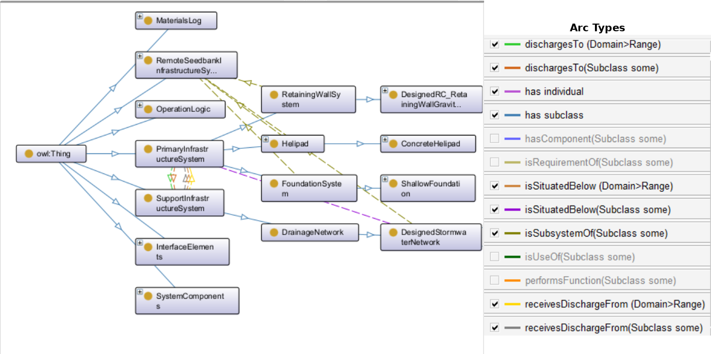
Figure 1. OntoGraf view of the combined ontology, showing the Remote Seedbank Infrastructure System, its primary and supporting subsystems, and their semantic relationships (arc types).
The three alternative seedbank configurations are represented as individuals within the ontology and correspond to conceptually distinct system variants defined in the parametric modeling domain, as described in the corresponding system-specific sections.
System Components and Subsystem Classification
To maintain clarity and avoid overlap between independently modeled systems, the combined ontology applies an explicit component classification. Infrastructure systems are decomposed into domain-specific components, allowing physical, network, and functional elements to be represented without duplicating system-level information. This structure preserves logical separation while maintaining explicit system relationships, enabling changes within one system without unintended effects on the integrated model.
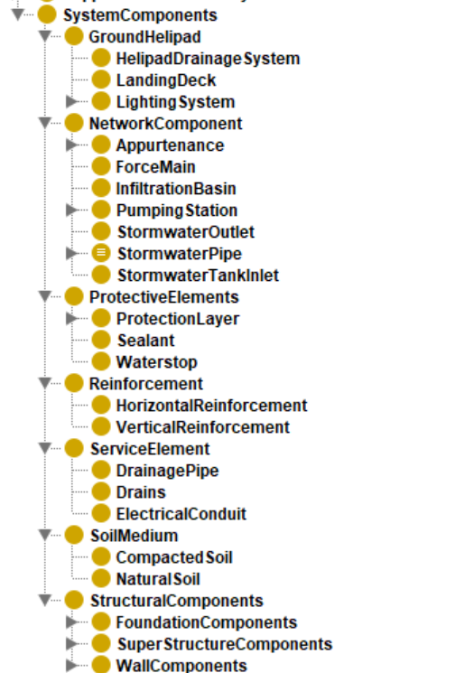
Figure 2. Class hierarchy illustrating the decomposition of system components into domain-specific elements, highlighting the separation between structural, network, service, soil, and helipad-related components within the combined ontology.
Explicit System Interaction
Beyond hierarchical organization, the combined ontology represents interactions between systems and components using a limited set of object properties. These properties make dependencies, interfaces, and connectivity explicit at the semantic level, such as subsystem relations, spatial positioning, and flow connections, while avoiding embedded analytical or numerical logic and preserving system modularity.
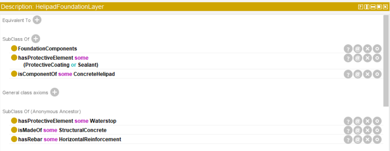
Figure 3. Example of object property axioms defining explicit semantic relationships between components, materials, and protective elements within the combined ontology.
Data Properties and Unit Consistency
Quantitative information in the combined ontology is represented using data properties that capture measurable attributes of components and systems, such as geometric dimensions, material characteristics, and performance-related parameters. These properties are assigned at the lowest logical level to avoid redundancy and to ensure that numerical values remain unambiguous.
To support consistency and future extensibility, each data property follows a fixed unit convention. While only selected examples are shown below, the complete list of data properties and their associated units is provided as a downloadable reference.
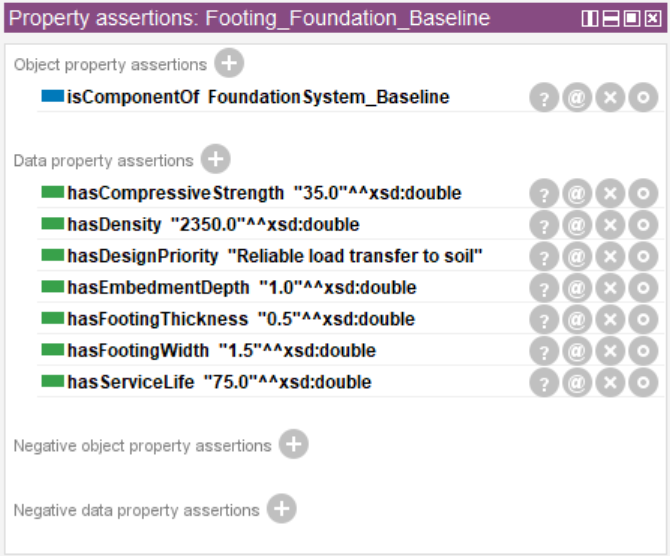
Figure 4. Data property assertions for a foundation component, demonstrating consistent assignment of quantitative parameters at the lowest logical level within the combined ontology.
Inference and Reasoning Results
To validate the internal consistency of the combined ontology and the integration logic across systems, reasoning was applied to infer class memberships and system relationships based on the defined axioms and property restrictions. The inferred results demonstrate how system-level entities correctly aggregate their respective subsystems and components without requiring manual reassertion.
The inferred hierarchies shown below illustrate that the combined ontology supports consistent reasoning across integrated systems, confirming that system structure, component responsibility, and interaction semantics align as intended.
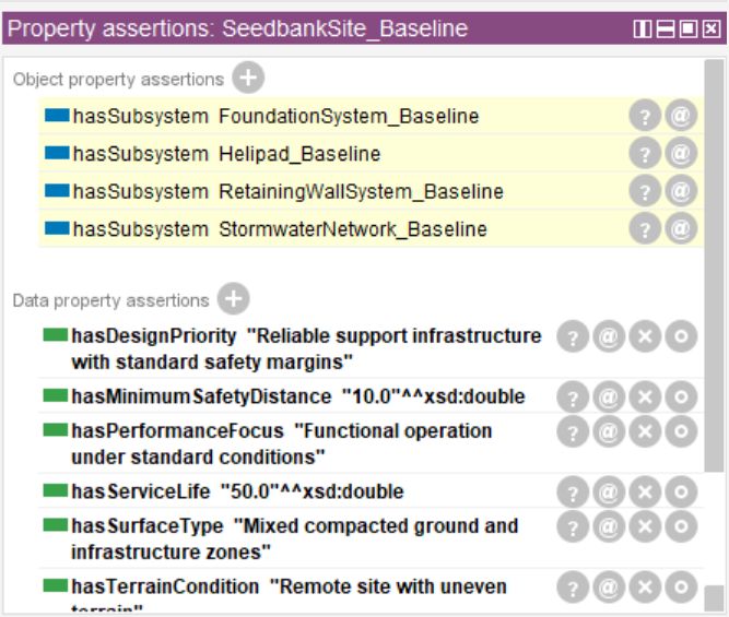
Figure 5. Inferred class hierarchy for the Seedbank site, illustrating automatic aggregation of foundation, helipad, retaining wall, and stormwater subsystems based on defined ontology axioms.
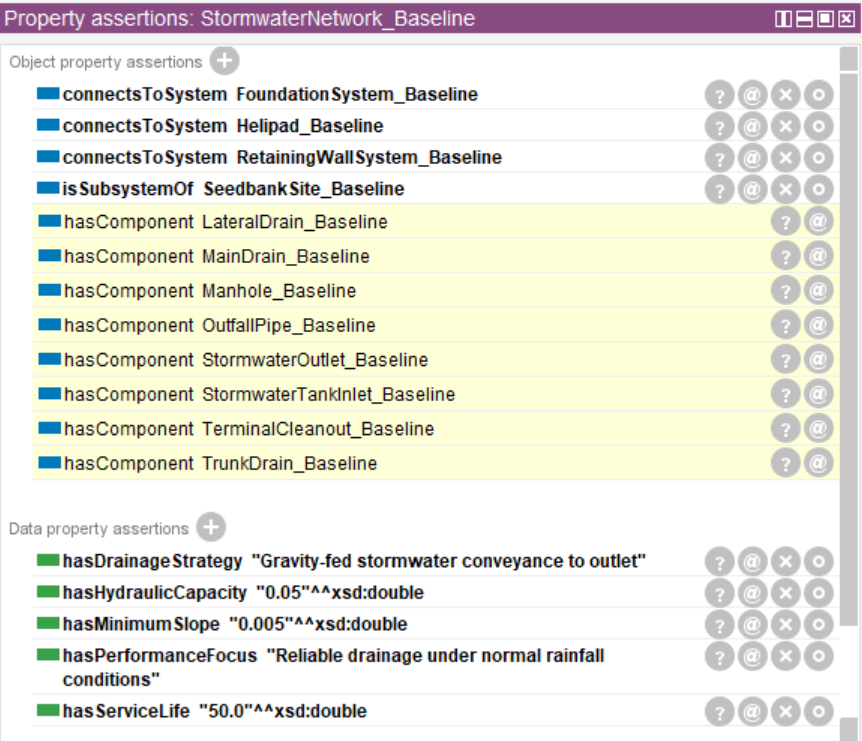
Figure 6. Inferred relationships for the stormwater network subsystem, showing inferred system connections, component aggregation, and associated performance-related properties.
Limitations and Future Improvements
- Quantitative detail: Data properties and numeric constraints (e.g., capacities, dimensions, safety factors) are only partially defined and can be extended for deeper reasoning.
- Spatial & dynamic aspects: Spatial context and lifecycle or operational behavior are modeled conceptually and could be refined through tighter BIM/geospatial and temporal integration.
- Semantic–parametric coupling: Future work could strengthen automated links between ontology semantics and parametric design workflows.
Final Ontology File
REFERENCES
1] Noy, Natalya F., and Deborah L. McGuinness. Ontology Development 101: A Guide to Creating Your First Ontology. Stanford Knowledge Systems Laboratory, 2001.
Home | Introduction | Individual Systems | Integration Context | Combined Parametric Model