Integrating the system for the future seedbank required coordinating four basic but interdependent systems within a constrained high-terrain setting. The retaining wall defines the change in elevation and limits how close the helipad and the strip foundation can be placed, while the drainage system must pass through the site without interfering with either structural element. Because the terrain is steep and rainfall is expected, the layout had to ensure that all components work together under gravity and that no system obstructs the function of another. The main challenge was therefore not complex design, but arranging these four systems retaining wall, helipad, drainage, and foundation in a consistent and realistic way that reflects how such infrastructure would be planned in an early engineering stage as shown in the figure.
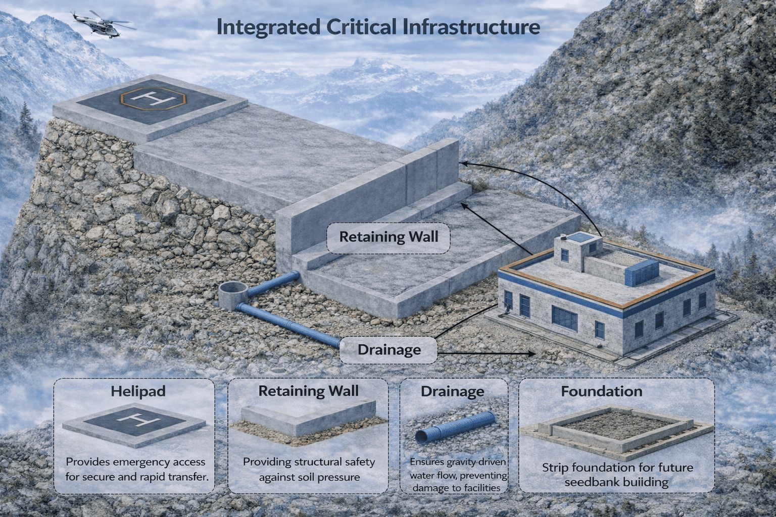
Figure 1: Illustration of the Integration Context
Gravity Retaining Wall
Serves as the central structural element that separates the upper and lower terrain levels. It stabilizes the soil mass behind it and defines the spatial limits within which the helipad and foundation can be safely placed. The retaining wall also acts as the reference element for proximity and safety checks within the integrated system.
Helipad (Upper Platform)
Provides emergency access to the seedbank site when road access is limited or unsafe. Its placement on the upper elevation must respect the retaining wall’s influence zone to avoid compromising stability. The helipad is therefore directly constrained by the retaining wall geometry and elevation.
Strip Foundation (Lower Platform)
Represents the permanent structural base for a future seedbank building. Its location is fixed on the lower terrain and must remain outside unsafe proximity to the retaining wall. The foundation also serves as the downstream point for site drainage, linking it functionally to the drainage system.
Gravity-Based Drainage System
Collects and conveys runoff from the upper platform toward the lower elevation under gravity. It prevents water accumulation and waterlogging around the retaining wall and foundation, supporting long-term serviceability. The drainage system physically and functionally connects all elevation levels and must remain compatible with both structural systems.
Components added: Concrete platform
A thin concrete platform (approximately 10 cm) is introduced at the upper elevation to provide a stable and level surface for placing the helipad within the model. Its purpose is not detailed structural design, but to ensure consistent geometry, alignment, and positioning of the helipad during parametric testing. This layer enables clear definition of elevation and avoids unrealistic placement on uneven terrain.
Interaction Between Systems
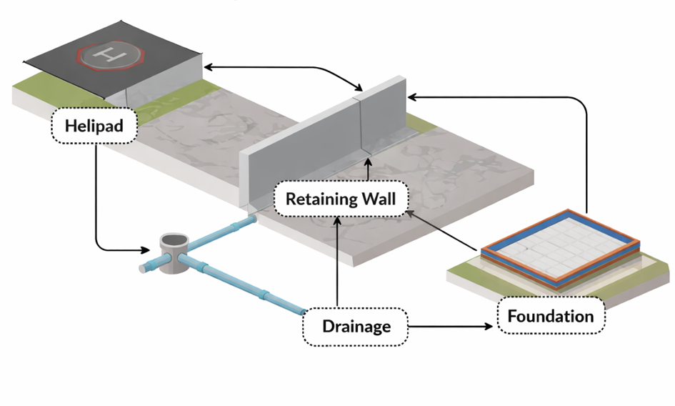
Figure 2: Representation of Interaction between systems
Foundation
Connected to the retaining wall through proximity constraints and to the drainage system as the downstream element that must be protected from water accumulation and waterlogging.
Retaining Wall
Acts as the central system connecting the helipad, foundation, and drainage. It defines the elevation difference, constrains safe placement of adjacent systems, and provides a controlled interface for drainage passing between levels.
Helipad
Connected to the retaining wall through safety and placement constraints on the upper platform and indirectly linked to the foundation through shared spatial limits defined by the wall.
Drainage System
Connected to both the retaining wall and the foundation, conveying runoff under gravity from the upper platform past the wall and toward the lower elevation to prevent water accumulation around structural elements.
Key Parameters of the integrated system
1. Retaining Wall Height (H)
Governs the vertical separation between upper and lower terrain levels. This parameter directly controls the required safety distances used in HF1 and influences the spatial feasibility of placing the helipad and foundation.
2. Horizontal Distance to Helipad (dH)
The plan-distance between the retaining wall crest and the helipad. This parameter is evaluated in HF1 to ensure the helipad remains outside the retaining wall’s influence zone.
3. Horizontal Distance to Foundation (dF)
The plan-distance between the retaining wall toe and the strip foundation. This distance is checked in HF1 to confirm safe placement of the foundation relative to the wall.
4. Drainage Pipe Slope (S)
Defines the gravity-driven inclination of the drainage system. This parameter is critical for HF2, determining whether water can flow without mechanical assistance.
5. Drainage Pipe Diameter (D)
Controls basic flow capacity and constructability of the drainage system. Along with slope, it is a primary input for HF2 functionality checks.
6. Pipe Material Roughness (Manning n)
Represents hydraulic resistance of the drainage pipe material. A fixed value is used in HF2 to ensure consistent evaluation of gravity-driven flow behavior.
High Performance Criteria 1 : Spatial Safety with Respect to the Retaining Wall
HF1 assesses whether the helipad and strip foundation are positioned at a safe distance from the retaining wall using a conservative, geometry-based rule tied directly to wall height. In this project, the minimum required distance is defined as twice the retaining wall height (2 × H), providing a safety margin appropriate for high-terrain and rainfall-exposed conditions.
- Uses the retaining wall height (H) as the primary reference parameter.
- Defines the minimum safety distance as 2 × H for both helipad and foundation placement.
- Compares this required distance against the actual geometric distance measured in the model.
- Ensures that both systems remain outside the retaining wall’s influence zone.
- Produces a clear OK / Too Close output to support early-stage layout decisions.
High Performance Criteria 2 : Gravity-Based Drainage Functionality
HF2 evaluates whether the drainage system is capable of operating under gravity while also assessing basic hydraulic performance using a simplified flow formulation. It’s function is therefore divided into two equally important aspects:
1. Gravity functionality check
Verifies that the drainage pipe has a positive slope and correct flow direction, ensuring water can move from the upper platform toward the lower elevation without mechanical assistance. This check confirms basic feasibility in a high-terrain, rainfall-prone environment.
2. Hydraulic performance using Manning’s equation (HDPE pipe)
Uses the Manning equation to estimate flow behavior under full-pipe conditions, considering pipe diameter, slope, and material roughness. The pipe is modeled as HDPE, a common drainage material due to its smooth internal surface, durability, and resistance to corrosion. A low Manning roughness coefficient is adopted to reflect realistic gravity drainage performance at an early design stage.
Together, these two components ensure that HF2 captures both geometric feasibility and simplified hydraulic viability of the drainage system.
Home | Introduction | Individual Systems | Combined Ontology | Combined Parametric Model