Design Scenarios
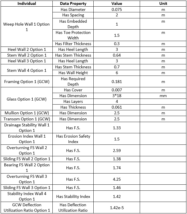
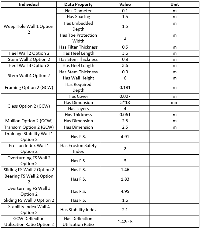
Three design scenarios are considered in this project. For each scenario, specific design options are represented as ontology instances, and corresponding data properties are assigned.
└─Scenario 1: Baseline Design
This scenario represents a balanced reference configuration. All components are designed to satisfy safety and serviceability requirements under normal site conditions without introducing unnecessary conservatism. Drainage performance, excavation boundary stability, visitor circulation, and lower-slope stabilization are addressed at a standard level.
└─Scenario 2: Rainfall and Slope-Controlled Design
This scenario focuses on conditions in which rainfall and slope behavior become more critical. Design modifications primarily target retaining walls that interact directly with water and soil movements, while other components are adjusted only as necessary to maintain system compatibility.
└─Scenario 3: Visitor and Heritage-Controlled Design
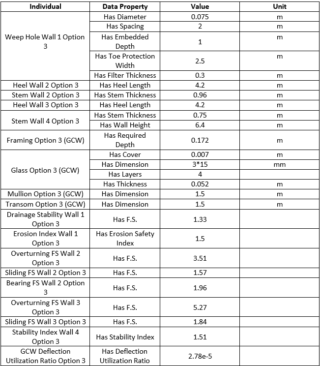
This scenario prioritizes visitor safety and archaeological site protection. Excavation boundary retaining walls are strengthened, and the glass curtain wall is made stiffer by reducing panel size. Drainage and lower-slope stabilization measures remain close to the baseline design to preserve overall system balance.
Ontology Structure
Class Decomposition
The ontology represents the archaeological site as a system composed of following main Classes.
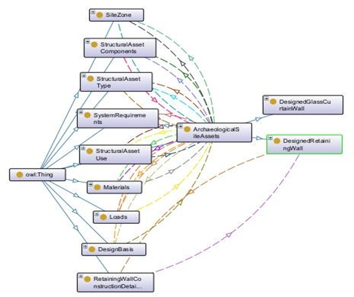
└─Archaeological Site Assets
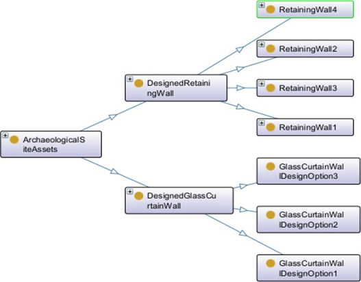
The archaeological site consists of two types of structural systems: retaining walls and a glass curtain wall. The properties of these systems, together with their relationships to other ontology classes, define the semantic structure of the site design. Each design option represents one of the defined design scenarios. All four retaining walls are instantiated for each scenario, resulting in three distinct instances per retaining wall corresponding to the three design scenarios considered in the project.
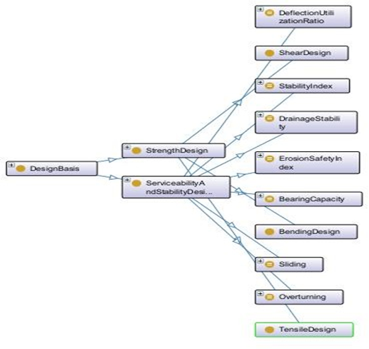
└─Design Basis
The design basis defines the evaluation framework used to assess different design options. Evaluation concepts such as drainage stability, overturning and sliding control are associated with designed items to document performance.
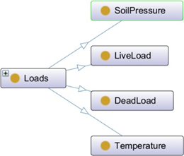
└─Loads
Load concepts represent actions against which the systems are designed. Earthquake loading is excluded, as the site is not intended to remain operational under seismic conditions and archaeological assets would be removed in such sites.
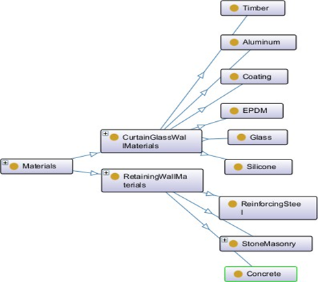
└─Materials
Material classes are defined separately for retaining wall systems and the glass curtain wall system and are assigned to designed items based on structural type. (e.g., masonry for gravity retaining wall).
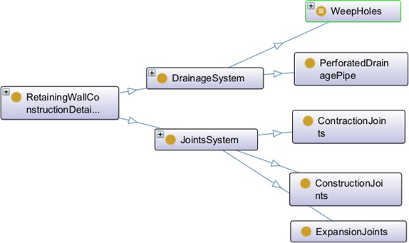
└─Retaining Wall Construction Detail
Construction detail concepts are included for retaining wall systems, particularly those related to drainage design. These details are essential for representing rainfall-driven safety scenarios
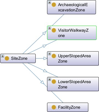
└─Site Zones
The site is divided into functional zones to clarify system configuration and usage. Each designed item is explicitly associated with its corresponding zone, enabling clear categorization and interpretation
└─Structural Asset Components
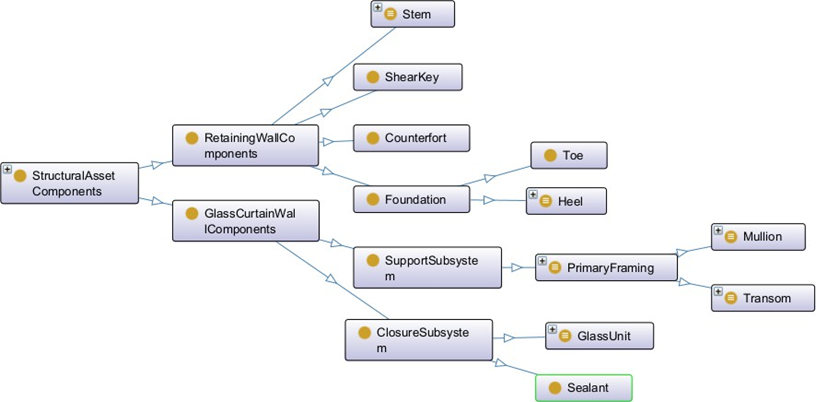
Structural components represent the physical makeup of retaining walls and the glass curtain wall. Mandatory and optional components are addressed through restrictions, and components are adapted to support system-specific roles.
└─Structural Asset Type
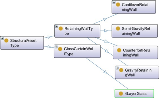
Structural asset types define permissible configurations and enforce constraints, such as material and reinforcement requirements for different retaining wall types.
└─Structural Asset Use
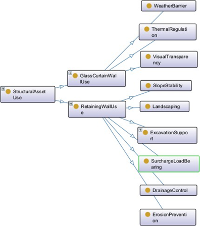
Each structural asset may serve one or more functions within the system. These uses are explicitly represented to clarify functional intent.
└─Systems requirements
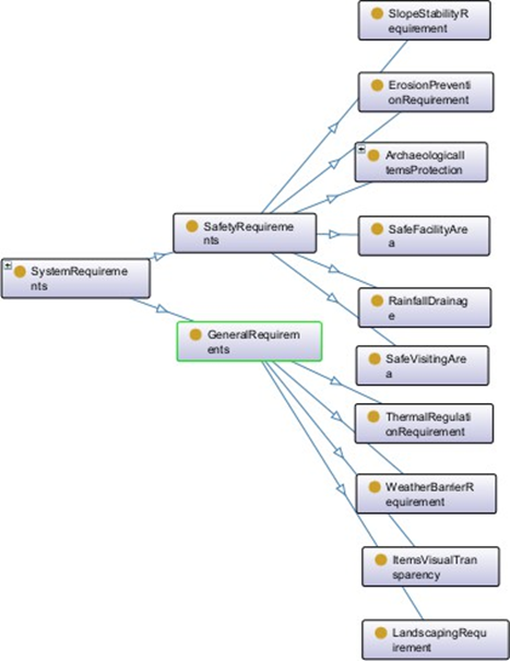
This site, considered as an integrated system, has specific requirements that must be fulfilled in order to function properly. Accordingly, site requirements have been identified and explicitly related to each designed item to clarify its role within the system and to ensure that all site requirements are satisfied. The site requirements are divided into two categories: general requirements and safety requirements.
General requirements are not directly related to safety aspects but are necessary to ensure the appropriate use and functionality of the site. Safety requirements, on the other hand, must be carefully addressed, as they represent the essential and dominant design concern and constitute the main challenge of such a project.
Main Object Properties
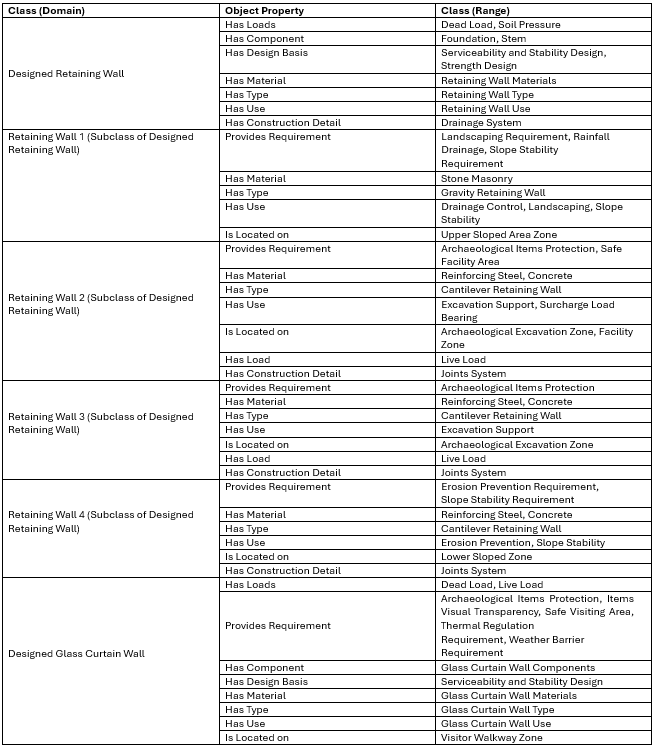
These relations represent the main connections within the system. They clarify the properties of each designed item and define how the designed items are organized and connected to one another within each site zone. Through these relations, the individual systems collectively serve the overall system by fulfilling the defined site requirements.
Main Data Properties
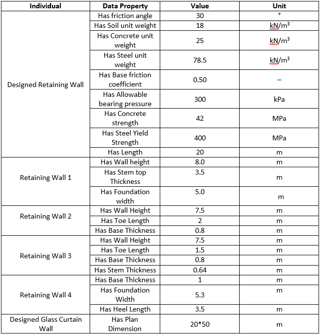
The following data properties have been defined for the designed items and assigned to each design option corresponding to the three considered scenarios.
└─General Fixed Data Properties
└─Scenario 1 Data Properties
└─Scenario 2 Data Properties
└─Scenario 3 Data Properties