This study focuses on a nearshore–offshore integrated infrastructure system composed of multiple engineering subsystems, shown in Fig. 1. Centered on energy supply and nearshore service functions, the system mainly consists of two offshore wind turbines and a group of onshore infrastructures. One wind turbine is located in the nearshore area and adopts a gravity-based foundation (OWT 1), while the other is installed in the offshore area and uses a jacket-based foundation (OWT 2); together, the two turbines provide electrical power to the onshore systems. By deploying two wind turbines at different locations and with different foundation types, the system effectively reduces the impact of a single turbine shutdown on overall energy supply, while also increasing the independence of their maintenance activities. The nearshore raft mat foundation serves as the load-bearing structure, supporting a commercial building and a parking deck that accommodate human activities and transportation demands.
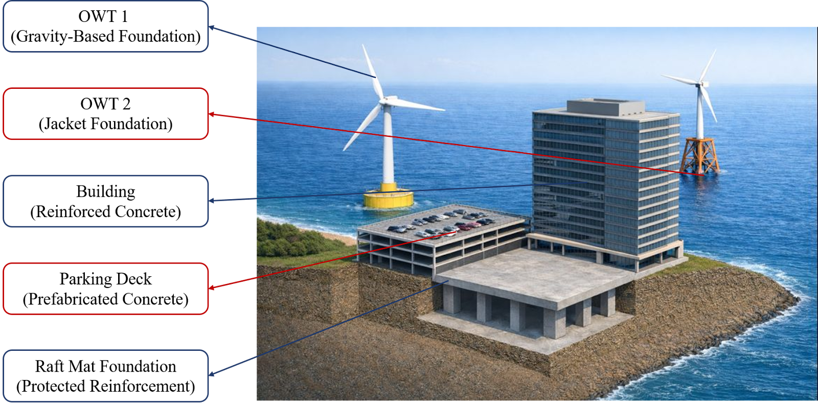
Fig. 1 AI-generated using DALL·E through ChatGPT (OpenAI, 2025).
The integrated systems in this context are:
OWT 1 — Provide Electricity Power
OWT 2 — Provide Electricity Power
Parking Deck — Provides parking capacity and access infrastructure for the commercial building
Building — Provides parking capacity and access infrastructure for the commercial building
Raft Mat Foundation — Supports the commercial building & parking deck
Each system has an optimal design option based on its structural and functional requirements. Table 1 presents the best design solutions for each system.
Table 1

The OWT 1 adopts a gravity-based foundation, composed primarily of a reinforced concrete structure combined with sand and gravel ballast. This solution is well suited for nearshore areas with relatively shallow water depths and stable geological conditions.
The OWT 2 employs a jacket-based foundation structure. Compared with gravity-based foundations, jacket foundations exhibit better adaptability in offshore environments characterized by greater water depths and more complex environmental loads.
The onshore parking facility adopts a prefabricated concrete slab system as its primary structural form. Prefabricated components can be manufactured under controlled factory conditions, improving quality assurance while reducing interference with surrounding buildings and ongoing functions.
The main structural system of the commercial building consists of a reinforced concrete beam–column frame. This structural form offers a balanced performance in terms of load-bearing capacity, spatial flexibility, and long-term durability.
The raft mat foundation serves as the shared foundation for both the onshore building and parking facility and is designed as a reinforced concrete structure with protected reinforcement. Protective measures for the reinforcement help enhance structural durability and reduce the adverse effects of crack propagation and steel corrosion on long-term performance.
Integrated Maintenance Effects
Within this nearshore–offshore integrated infrastructure system, maintenance activities of individual subsystems are not independent, but instead interact at the operational, resource, and spatial levels.
During foundation inspections, structural repairs, or electrical system maintenance, offshore wind turbines typically require temporary shutdowns or reduced power output, which may cause instability in electricity supply for the onshore systems during certain periods. Although the coordinated operation of the two turbines improves overall system reliability, overlapping maintenance schedules may still affect the continuous operation of the commercial building and parking facilities.
Maintenance of offshore wind energy facilities relies heavily on vessels, lifting equipment, and port resources, which are often limited and shared at the regional scale. To mitigate potential resource conflicts, the two wind turbines are spatially separated into nearshore and offshore locations, allowing greater independence in terms of shipping lane usage, vessel scheduling, and maintenance windows. For example, maintenance operations for the offshore turbine typically do not occupy nearshore shipping lanes or interfere with coastal maritime traffic, thereby reducing impacts on nearshore system operations.
On the onshore side, maintenance activities for the raft mat foundation, commercial building, and parking facilities—such as structural repairs, waterproofing replacement, or surface maintenance—often require temporary occupation of workspaces or restrictions on pedestrian and vehicular access. For instance, partial closure of parking areas or rerouting of circulation paths may reduce system availability and inconvenience daily building use.
Under this integrated context, system maintenance is no longer a localized issue confined to a single subsystem, but rather a coordinated decision-making problem involving multiple systems across the lifecycle scale. Therefore, in the subsequent sections, the design of maintenance strategies, life-cycle environmental impact assessment, and multi-objective optimization are analyzed within this integrated system framework.
Image Reference: OpenAI. (2025). AI-generated illustration of Fig. 1 [Digital image]. Generated using DALL·E through ChatGPT.
Home | Introduction | Integrated System | Maintenance Strategies | Life Cycle Analysis | Multi-Objective Optimization | Conclusion and Limitations