Parametric Definition of a Truss:
For roof trusses in e.g. halls, external boundary conditions such as span, roof pitch / chord slope and construction depth are usually dictated by the building layout. The actual design freedom for structural engineers therefore lies inside the truss: in the web system (web pattern), cross-sections and material choice.
Outer geometry / fixed parameters – Span of the truss L – Minimum truss height at the supports HMin – First height at midspan HFirst, defining the slope of the top chord
Web system / truss scheme – Number of panels: panel count – Presence of end posts: hasEndPosts and intermediate posts: hasVerticals – Orientation pattern of diagonals (diag_dir: towards support, towards center, alternating)
Material configuration – Separate for chords and web members: tensile and compressive strength, density ρ – Cross-section dimensions: b, h – only full cross sections
Loads – Roof line load q and the equivalent self-weight line load resulting from the truss
Role of the Parameters:
The span L determines the bending moment level and thus the axial forces in the chords (derivations are provided in the appendix). In practice, the building layout – and therefore L – as well as clear hall height, maximum building height and roof pitch are usually fixed; from these, HMin and HFirst follow. In the model, these quantities are treated as fixed boundary conditions.
In addition to HMin , the panel count controls the panel lengths and the diagonal angles. The web parameters hasEndPosts, hasVerticals and diag_dir govern the internal force flow: Pratt systems favour tension diagonals and compression posts, Howe systems favour compression diagonals and Warren systems alternate tension and compression in the diagonals.
The cross-section dimensions b, h determine the area A, which together with the roof line load q and the self-weight g yields the design stress σd; the strength classes define the design strengths fd,t and fd,c , so geometry and material jointly link the parametric model to structural capacity.
Defining Input Parameters:
For a hall scenario with fixed roof pitch, clear height, hall width and a given roof load, the following parameters are fixed:
| Input Parameter | Value |
| Force q | 7 kN/m |
| Span length L | 7 m |
| MinHeight HMin | 1 m |
| FirstHeight HFirst | 2 m |
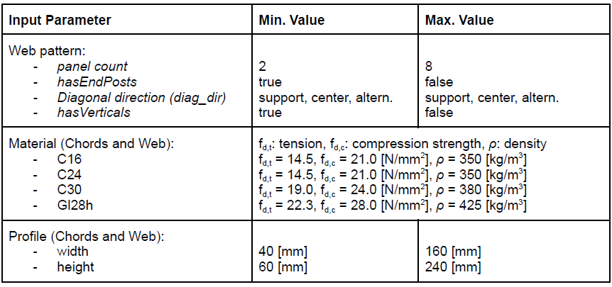
The following parameters are available for optimization (applied uniformly to all chords and all web members/posts, respectively):
Logic of the Parametric Model (Dynamo):
The Dynamo script can be roughly divided into three blocks:
First Block: Inputs On the left, all inputs are defined. Helper blocks process these inputs: for example, from the material choice (C16, C24, …) a set of material properties is derived and passed to the subsequent blocks.
Second Block: Geometry – nodes, members and solids A) First: all nodes of the truss are calculated: The Python node TrussPoints generates all truss nodes from L, HMin, HFirst and panel count: – bottom nodes equally spaced along the span, – top nodes forming a pitched top chord (interpolation between HMin and HFirst).
B) Second, all lines and solids for chords and web are built: From these points, chord members are created as lines; hasEndPosts controls whether the outer top nodes are connected. A second Python node generates the web system with: – verticals (posts) depending on hasVerticals, – diagonals according to DiagonalDirection (Pratt-, Howe- or Warren-like pattern).
These lines are then extruded in the BuildSolids block using the cross-section dimensions b and h to form simple 3D solids (rectangular sweeps). This makes the structure visible and allows member lengths to be read directly from the geometry.
Third Block: Calculations – loads, axial forces and stresses From the given roof line load q and the self-weight line load g (computed from geometry, cross-section area and density), a design line load Ed is formed. Using a deliberately simplified structural model, the following are derived: – the governing axial force in the bottom chord, and – the critical tension and compression forces in the diagonals. A Python node converts these axial forces together with the cross-sectional areas A into design stresses σd [N/mm²], distinguishing between tension and compression in chords and diagonals. In parallel, using kMod, γM and the material strengths, the design strengths in tension fd,t and compression fd,c are calculated.
Performance indicators:
From stresses and strengths, the utilization ratios η are computed for bottom chord and diagonals. In addition, the truss self-weight G is output as total mass [kg].
Design alternatives:
For the variant study, a common framework is defined: Span length L = 7 m, HMin = 1 m, HFirst = 2 m and roof line load q = 7 kN/m To reduce degrees of freedom, the web pattern is fixed as: hasEndPosts = true, hasVerticals = true, diag_dir = support (Howe-like). Chord parameters are kept constant (h = 160 mm, b = 240 mm, material = C16); only the diagonal parameters are varied.
The study investigates whether a higher panel count, larger cross-sections b, h or a higher strength class fd (at the cost of higher density ρ) leads to better material efficiency. Three representative variants are considered:
- few panels, relatively large profiles, C16 (standard material)
- B) more panels, slender profiles, C16 (standard material)
- C) more panels, slender profiles, GL28h (higher-strength, higher-density glued-laminated timber)
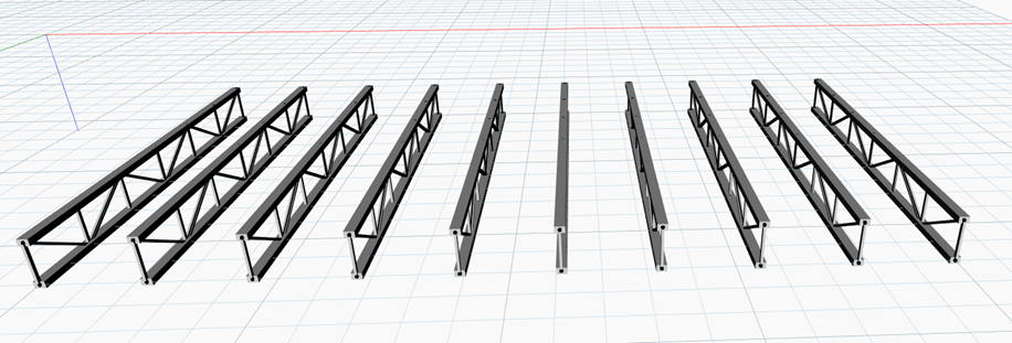
Figure 01: Dynamo Model