The integrated system investigated in this project consists of gravity retaining walls, cantilever retaining walls, a reinforced concrete slab, a precast concrete frame, and an external thermal insulation composite system (ETICS). The systems of precast concrete frame, reinforced concrete slab and the ETICS make up the basis of a building. The two types of retaining walls provides foundation support for the structure.
The system is located in a hilly terrain with asymmetric boundary conditions, characterized by water exposure on one side and a steep cliff on the other, requiring a dedicated retaining wall for each side. The concrete slab is structurally integrated into the precast concrete frame, while the ETICS forms the building envelope and is directly influenced by the geometry and behavior of the load-bearing structure. This scenario reflects structures built on challenging terrain scenarios such as a dam monitoring facility structure.
These subsystems are interdependent and interact throughout their life cycle. The precast concrete frame defines the building dimensions and load paths, influencing both the concrete slab and the insulation system, while its self-weight and imposed loads contribute directly to the vertical and horizontal forces that must be resisted by the retaining walls. The retaining walls and the superstructure are therefore connected through a structural load-transfer interface, where movements or differential settlement of the walls can affect the alignment and structural performance of the frame. Due to the differing environmental exposures, the retaining walls experience different deterioration and corrosion rates, further differentiating their maintenance requirements. These interfaces are visualized in figure 1.
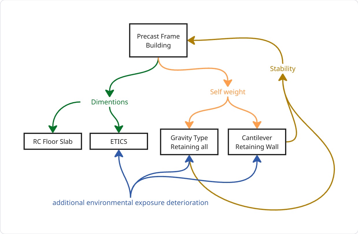
Addtionally, the concrete slab and precast frame form a composite load-bearing system in which cracking, deformation, or deterioration of one component alters stress redistribution and load paths in the other. The ETICS, directly attached to the precast frame, is sensitive to structural movements, cracking, and thermal deformation, which can lead to cracking, detachment, or moisture ingress and influence its maintenance frequency. The complex terrain and shared interfaces between subsystems further constrain access and sequencing of interventions, making isolated maintenance impractical. Consequently, integrated maintenance strategies are required, and different maintenance scenarios are investigated to evaluate which best meets the defined objectives in terms of system performance, service availability, and life-cycle sustainability.
Throughout the lifetime of a civil system, various actions and decisions are made to improve the systems performance and extend its functional lifetime, defying failure and deterioration of its components. Meticulous planning is essential to guarantee seeking optimum strategies needed to carry out maintenance activities that prevent repetitive closure of facilities, additional costs and spontaneous interventions for complex systems, Crespo described the process as “establishing a good maintenance program is an interdisciplinary enterprise that requires both managerial/organizational expertise and quantitative analysis that utilizes mathematical models.” [1] , which in turn describes the quest of this assignment. This will be done through the following steps:
- Integrating different Maintenance actions through defining different Parameters, and then analyzing each scenario through:
- Creating a Life Cycle Analysis of the integrated system
- Solving a Multi-Objective Optimization problem to define the overall best performing strategy
- Discussing Results and Findings
The starting point in Maintenance planning is demonstrated in Table 1, as it summarizes the maintenance actions, their duration and expected interruption time for all 4 individual systems.
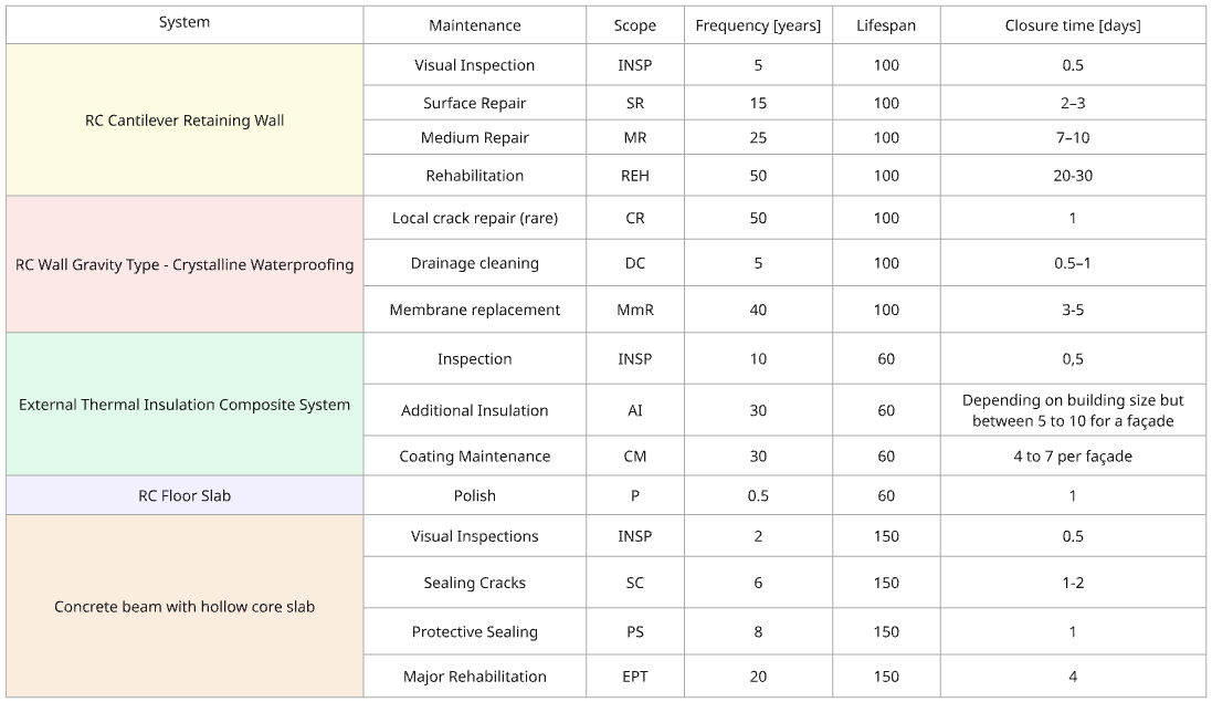
The following part describes technical details that are carried out along the workflow of this project, and used to perform the analysis on all four scenarios.
Optimizing Maintenance strategy
A computational optimization model was developed to seek the optimal maintenance strategy of the selected integrated maintenance activities using R software ( R code is provided in the Annex ). The model starts by creating design alternative space, of which all possible scenarios pairing the possible maintenance frequencies for different intervention types. Having these upper and lower bonds of the maintenance action frequencies added flexibility for better pursue of possible maintenance strategies. The original optimization model used the frequency ranges to implement all possible scenarios, but due to the number of systems integrated, the model used for this project depended on sampling values of frequencies instead. This was also refered to by De Weck by: “A comprehensive or full-factorial evaluation of the design space is often impossible due to the n-dimensionality of the design vector, x, and the required computational effort for obtaining J, g and h” [7].
Life Cycle Assessment & Multi-Objective Optimization
Reoccurring maintenance activities carryout an environmental fingerprint due to material and energy consumption needed to carryout these activities, thus it is important to investigate environmental performance of different strategies to ensure balance between environmental, monetary and timely cost of different strategies.
Investigating the environmental impact of the maintenance, a Life Cycle Assessment over the system (LCA) lifetime is performed using R code. This is built on top an LCA performed on individual systems in a previous report [2], [3], [4], [5], and will be extended in this study to include the environmental footprint of maintenance activities, taking into consideration the integration context of these systems.
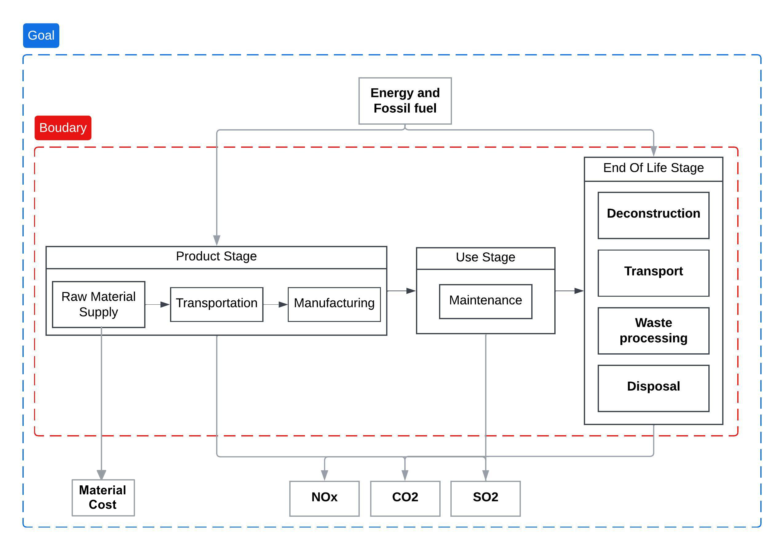
The LCA starts by first defining a clear goal and scope; for this study the goal is to determine the integrated system environmental impact according to the following indicators : CO2, SO2, and NOx emissions caused by embedded energy and fossil fuel consumption, during the main stages of the system; production, use, end of life, and most importantly in this context, maintenance, as shown in figure 2
The scope of this assessment is a two story precast concrete building equipped with an External Thermal Insulation Composite System in a special terrain requiring two types of retaining walls, gravity type and cantilever supporting the soil around the foundation of this building. The dimensions of the system are shown in figure 3 , studying a 6m segment of the represented structure.
Second comes Life Cycle Inventory (LCI) step, where data is collected on the individual impact of the raw materials of different components, again based on the referred previous projects. The maintenance impact is considered as a percentage of the total sub-system materials, that is consumed during each maintenance action, monetary cost is also added as a factor in this stage. breaking out the impact of different used components.
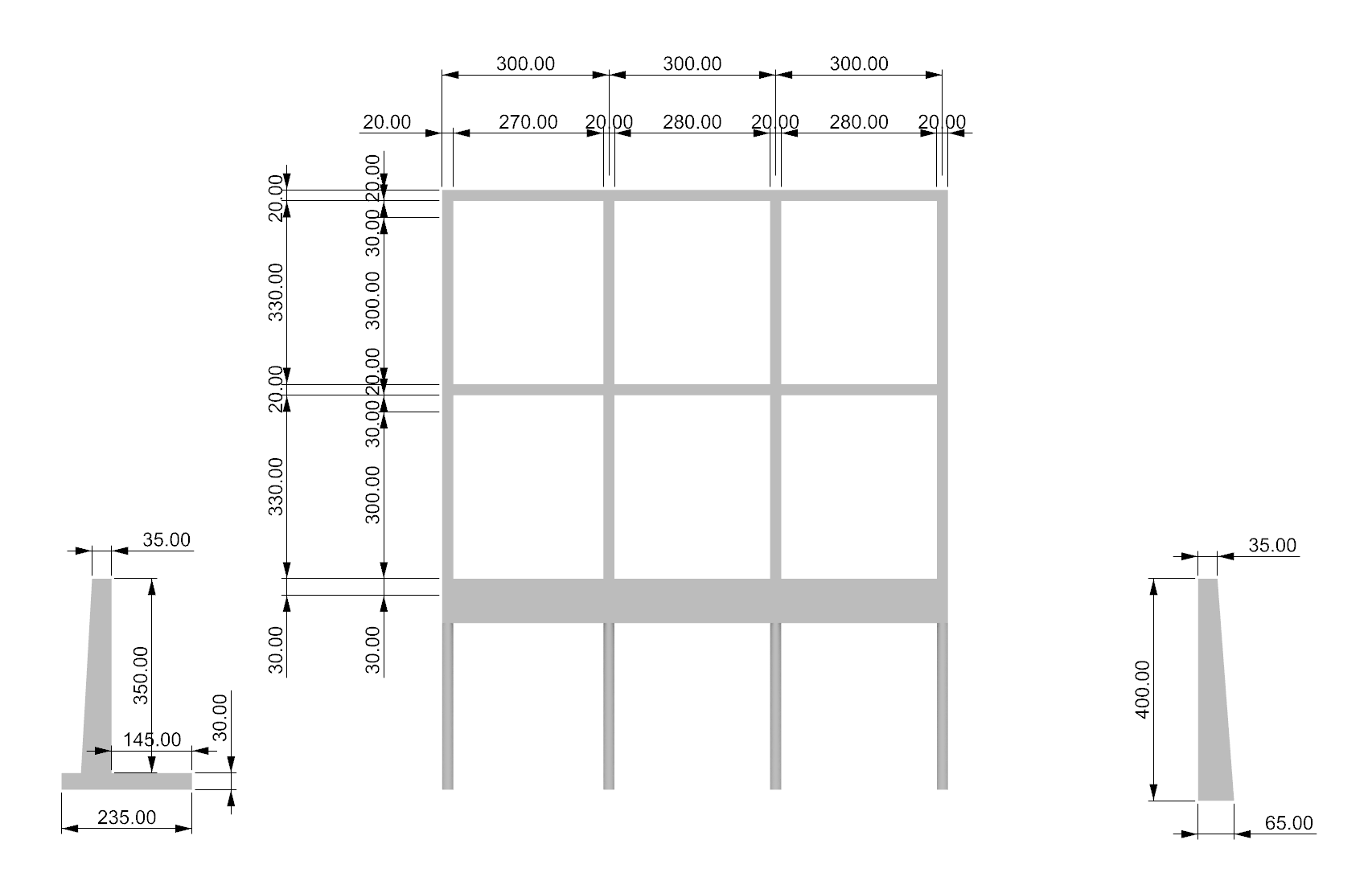
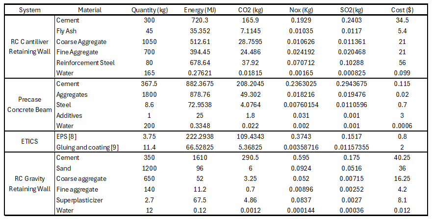
Table 2 summarizes the material quantities defined for the main structural components considered in the analysis, together with their corresponding environmental indicators. These values were used as fixed input parameters in the optimization analysis performed in the R environment.
Multi-Objective Optimization is done using NSGA-II method, a Non-Dominated Sorting Genetic Algorithm II introduced by Deb et al. [6]. This method does not prioritize on objective over the other through weighing, rather treating all objectives equally. The solutions introduced through LCA are ranked according to the pareto dominance. The alternative space is reduced by clustering points with small crowding distance and isolating the large crowding distance, but with prioritizing the isolated ones to ensure that there will be no bias toward one objective extreme, and ensure even coverage of trade-offs. That is reflected in our case in spanning ( low-cost / high-disruption ) to ( high-cost / low-disruption).
Home | System Definition | Scenario 1 | Scenario 2 | Scenario 3 | Scenario 4 | Discussion | Appendix